
|

|
Forum Index : Electronics : Excel Sheet for Transfo Design
| Author | Message | ||||
| Warpspeed Guru Joined: 09/08/2007 Location: AustraliaPosts: 4406 |
The online course is very likely correct as far as it goes.... If a power choke is used in a typical mains powered rectifier the ripple frequency might be 100/120 Hz for a full wave rectifier, and the ripple current high enough to generate some eddy current loss effect in the laminated steel core. That is all perfectly valid and correct. What your lecturer probably did not include, is that if the ripple frequency is 23Khz instead of 100/120Hz then the frequency will be about x200 times higher. That x200 rise in frequency means that the flux swing in the core (on top of any dc flux) will be 200 times less. And the actual losses in the core will be far lower than might be expected. Chokes are very different to transformers. With a transformer you need high a flux swing to transfer any power, and a laminated steel core will definitely be more lossy. But even an audio transformer can be made to work at 20Khz if it has thin laminations and the flux density is kept low. Back in ancient times, tube amplifiers worked fine with laminated steel output transformers. The biggest problem with those at high frequencies was winding capacitance, not the laminated steel core. A choke on the other hand, has a lot of dc flux and an air gap. The ac flux can be quite low if there are sufficient turns on the core. And the higher the frequency, the magnitude of the ac flux reduces as Xl increases directly with frequency. Electrical theory as taught is perfectly valid in the right context. But at higher frequencies, other odd effects can predominate. Stray capacitance, parasitic inductance, and resonance effects can play havoc with simple ideas about alternating voltages and alternating current and Ohms law. Cheers, †Tony. |
||||
| azhaque Senior Member Joined: 21/02/2017 Location: PakistanPosts: 117 |
Thanks Warpspeed for your input. When I fired up my homebrewed inverter that doesnít have the choke installed, I found that when a load was connected to its output terminals it functioned normally. However when I connected it to the house distribution board it became unstable and voltage fell to 160 VAC. This would mean that the capacitance that the house wiring adds to the inverterís output makes it unstable. The above experiment makes me wonder if adding an iron cored choke of say 6.4 mH, IN SERIES WITH THE O/P TERMINAL, would solve the instability. In theory the choke will be reflected on the primary side and have a magnitude of 6400/64 = 100uH. In the transformer equivalent circuit, this 100uH will show up in series with the leakage reactance, thus supplementing the desired effect. An additional advantage would be that since no DC flows on the secondary side, we donít need to worry about the saturation effects. Finally on the practical plane, its much easier to wind a wire for 20 Amps than for 100 Amps. Useful idea or hot air? azhaque |
||||
| Warpspeed Guru Joined: 09/08/2007 Location: AustraliaPosts: 4406 |
All that is likely to do is make the voltage regulation very poor. I have no idea what is causing your problem, but you say connecting a load directly to the inverter it works o/k. One side of the mains wiring is (or should be) grounded. Could that be part of the problem ? The transformer secondary should be floating, but maybe there is something odd about the voltage feedback that goes crazy when one side of the output is grounded. Cheers, †Tony. |
||||
| azhaque Senior Member Joined: 21/02/2017 Location: PakistanPosts: 117 |
Hi Warpspeed. Yes, even without the choke installed, the inverter works when the load is attached to it without an intervening house wiring network. The answer to your second question is NO. Why- because I am off grid. I don't really need a ground since that is a requirement of the utility company. In any case I HAVE TWO COMMERCIAL INVERTERS (one having the same topology as the homebrewed one) running the house, without a grounded neutral. The sauce needs to work the same on the goose and the gander. There is another fact that I forgot to mention. There is a 5uF cap attached to the secondary. I removed it, thinking that the house wiring capacitance may be the cause of the instability. So I disconnected one leg of the 5uF cap. On switching on, the voltage ROSE to 326 VAC indicating some kind of resonance effect. I have ordered a choke. Hopefully when I get it, I will give it a try. Also I am thinking of making an iron cored choke, once the aliexpress choke arrives, for making a homebrew inverter using "WARPSPEED's MOSFET mounting method'. azhaque |
||||
| Warpspeed Guru Joined: 09/08/2007 Location: AustraliaPosts: 4406 |
Its really difficult to speculate about problems remotely Azhaque. Even if I was there myself to witness the whole thing, even then the issues and symptoms can be very confusing. Cheers, †Tony. |
||||
Revlac Guru Joined: 31/12/2016 Location: AustraliaPosts: 1026 |
azhaque Just looking at the unstable voltage and the pictures.. is there an isolation transformer connected to those purple and blue wires or not? Cheers Aaron Off The Grid |
||||
| azhaque Senior Member Joined: 21/02/2017 Location: PakistanPosts: 117 |
Thanks for the comeback Revlac. No there isn't. Directly from the secondary of the main transfo. azhaque |
||||
| azhaque Senior Member Joined: 21/02/2017 Location: PakistanPosts: 117 |
Revlac, Continuing from the previous post, I found a post from Oztules regarding this issue which seems to be haunting my inverter too. https://www.thebackshed.com/forum/forum_posts.asp?TID=8220&KW=Ozinverter&PN=1&TPN=2#94681 I quote the relevant portion This is the EG8010 circuit for the AC voltage sensing. 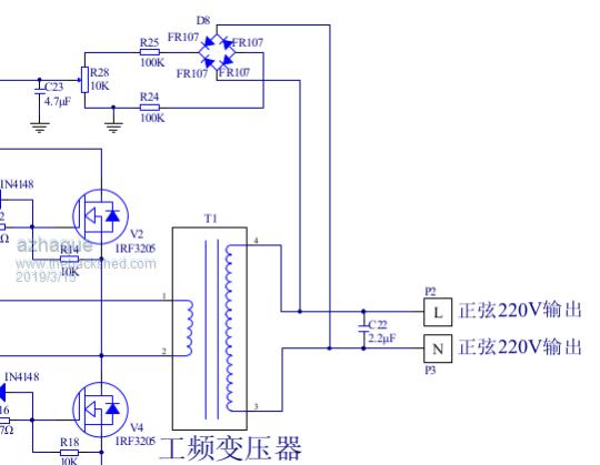 When I tested my inverter it also worked fine on 'the local load'. But when connected to the house wiring it went awry. Oztules thinks this may have to do with a ground after the bottom 100K resistor (R24), which probably upsets the whole feedback loop. So an isolation transformer is added. The datasheet says that the VFB pin (Pin13) on the chip needs 3 VDC. This suggests to me, that a small isolation transformer of 220/6 VAC be added and 100K resistor (R25) should be replaced by 22K and R24 jumpered. Any views on that? azhaque |
||||
| Tinker Guru Joined: 07/11/2007 Location: AustraliaPosts: 1904 |
We have been doing that for a long time now. Suggest you read some of the more recent inverter build posts here. You need to make the rectified feedback voltage from that little transformer adjustable to be able to set your AC output voltage. Klaus |
||||
Revlac Guru Joined: 31/12/2016 Location: AustraliaPosts: 1026 |
Most of us are using the isolation transformer for the VFB, It seems to work quite well. Also using 12v or 14v transformers but would have to change the resistors to suit. I had assembled a control board and found that I could not get a good voltage range when using the 500R trimpot and the same resister divider that others had used, due to the little transformer being a bit different output voltage than labeled, just changed the resistor value to suit. Bear in mind I don't know what those store bought boards have for a voltage divider. I was using a version of the OZ control board, be worth having a look at the configuration on one of those, or the Mad control board. I thank Poider for providing a good explanation about the reason why the isolation transformer was used. I had an idea why it was used ( I'm not very good at explaining things) and just went with it. Seems to be a few variations of inverter boards around on the market. Cheers Aaron Off The Grid |
||||
renewableMark Guru Joined: 09/12/2017 Location: AustraliaPosts: 1678 |
Tony would it be possible to use two stacked torroids with an air gap between them as a choke? Cheers Caveman Mark Off grid eastern Melb |
||||
| Warpspeed Guru Joined: 09/08/2007 Location: AustraliaPosts: 4406 |
No Mark, the air gap has to be in the magnetic path which goes around the toroid. Cheers, †Tony. |
||||
| azhaque Senior Member Joined: 21/02/2017 Location: PakistanPosts: 117 |
After the arrival from China, of a 47uH choke, I managed to install it in the inverter just before the mains transfo. Photos below of the choke in various stages of installation. 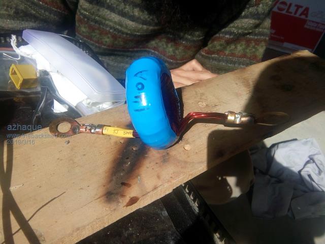 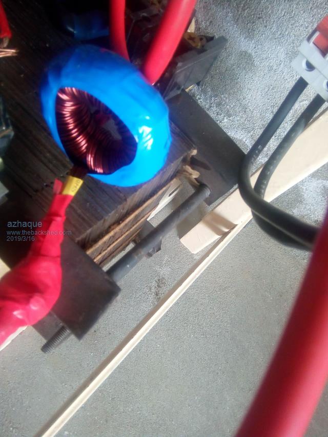 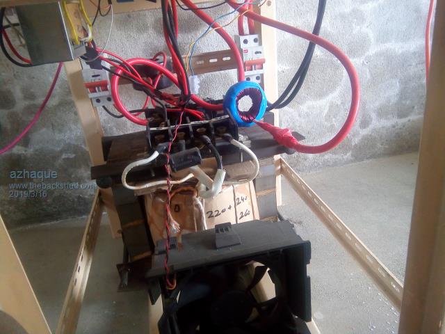 I also managed to modify the board for the feedback voltage by installing an isolation transformer. The circuit was also modified by removing some components and replacing these with others. The original and revised versions are drawn below. Starting with the circuit diagrams both the original and the modified versions photos are also reproduced below. 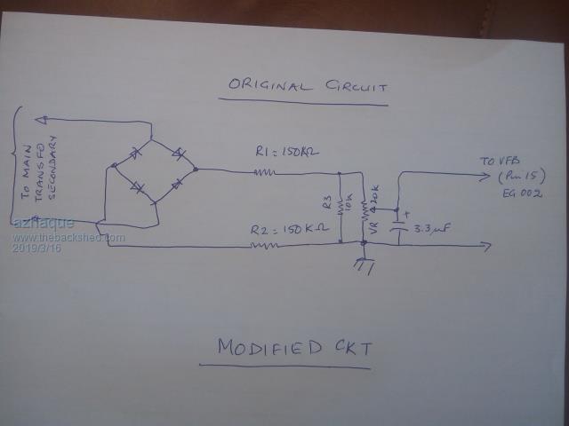 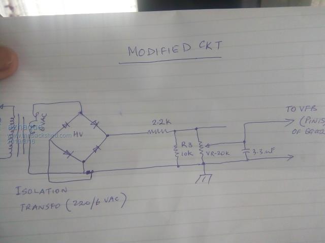 Below you can see the original circuit and the modified one with a jumper and a 2.2K resistor. 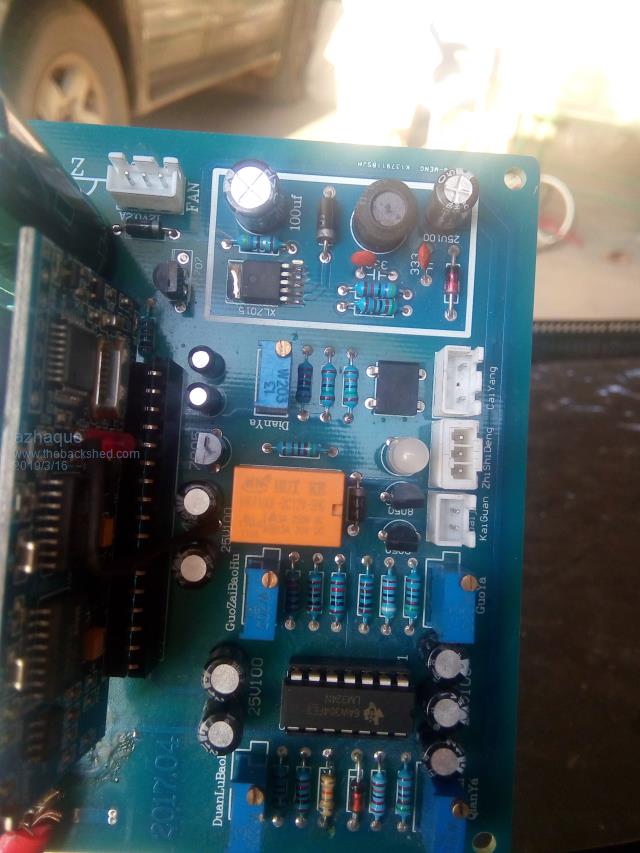 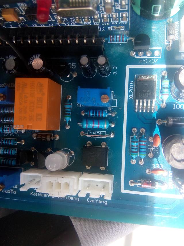 The 220/6 VAC isolation transfo can be seen close to the the upper left hand corner of the white mounting sheet, close to the connector strip. 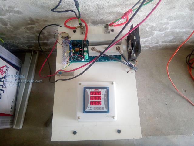 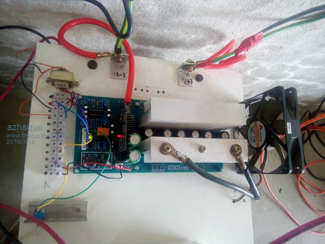 Youtube video of the inverter now connected to the house network and is currently being tested. Thanks to Warpspeed, Poida and Revlac for their help. LESSONS LEARNT 1. Can't avoid the choke in this topology. 2. Isolation transformer is also a must. TO DO 1. Install surge suppressors on MOSFET gates Regards azhaque |
||||