|

|
Forum Index : Electronics : Analog H-Bridge Driver
| Author | Message | ||||
| Solar Mike Guru Joined: 08/02/2015 Location: New ZealandPosts: 1138 |
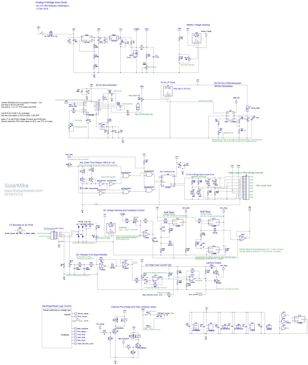
I have a portable Lifepo4 24Vdc HF 230vac inverter that I use to run power tools out in the field where there is no power, unfortunately after purchasing a new much bigger drop saw, it wont run off the power pack. Bugger, well I have this opto-isolated battery charger H-Bridge power board design and figured by changing its controller, it can be turned into a low freq inverter, with much higher startup overload capabilities. Not that happy with the existing EG8010 design and have had a concept design for an analog based driver sitting on various sheets of paper, this doesn't require any cpu to run. So over the past few days have been drawing up the schematic, testing each section on breadboard. The individual parts work well, so hopefully the whole design will be bug free. Will now focus on designing a pcb. The sine generator is based upon a XR2206 which ceased production years ago, but have been cloned by some clever Chinese and readily available on EBay, These clones are very much hit and miss, most will work, some wont. The distortion is really low and can be tweaked to approx 1%, the chip has a voltage feedback input that can be directly linked to AC voltage sensing to keep the output level constant. Sine output is feed into a precision modulator chip to produce infinitely variable sine based PWM, this can be used for Bi-Polar drive of the H-Bridge, in my case via opto-couplers. The carrier frequency can be set to any value within limits, I will be using 50 or 100Khz so the chokes are kept reasonably small. Dead time is accomplished by some Schmitt trigger gates, both falling and trailing edge can be precisely set measured at the gates of the main power board mosfets, ensuring any unequal delays in the system are countered for; using Warps opto drive here so no cross conduction is possible. The various LP filters are 24db/Octave State Variable 2 op amp design on a tiny plugin pcb, cleans up the noise from various signals being measured. A CPU isn't required to run this, but start/Stop sequencing logic would be better accomplished if a small picaxe or similar was used and to indicate any alarm or status points.  2018-12-13_131427_HB_Analog_Driver.pdf Cheers Mike |
||||
| Solar Mike Guru Joined: 08/02/2015 Location: New ZealandPosts: 1138 |
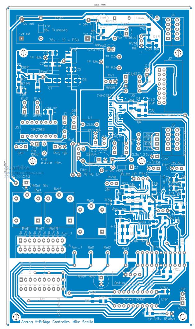
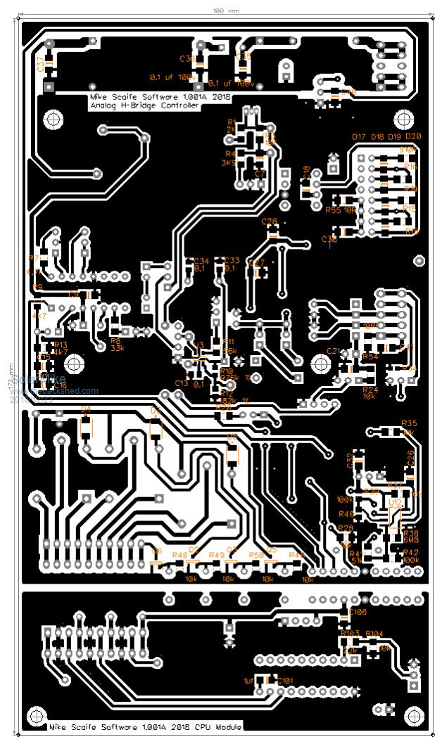
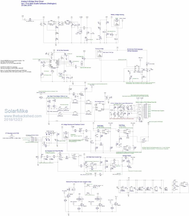
Have made some circuit alterations and fixed some potential issues discovered whilst designing the PCB layout. Rather than use manually controlled panel switches to get it going, have opted for a picaxe 20M2 to do the simple start\stop timing logic and connect to a LCD display. Control relays have been added to control the capacitor bank pre-charge and main contactor relays, with an aux relay + pull to gnd output for controlling a fan or alarm. The CPU add on module is attached to the end of the main PCB and can be cut off or easily exchanged for another CPU type. I have heaps of these picaxes lying around, so intend to use them up. PCB is quite complicated, once the schema is laid out in DipTrace then a board designed, it does have an auto layout facility, however its wizard is hopelessly inadequate when earthing has to be managed for the combinations of analog and digital signals, so gave up on its auto layout and did it the hard way, at least it tells you if a pcb connection doesn't match the schema. Top:  Bottom:  The multi-pin PCB connectors are push button spring type, where the bared cable is pushed in then locked, I have found these to be very reliable as the spring on each pin keeps the cable secure with constant tension. Having some issues with posting the schematic, its too big..... Cheers Mike |
||||
| Solar Mike Guru Joined: 08/02/2015 Location: New ZealandPosts: 1138 |
Schema: 2018-12-23_211543_Schema1.pdf  CPU: Cheers Mike |
||||
| poida Guru Joined: 02/02/2017 Location: AustraliaPosts: 1419 |
This looks interesting. I like the analog aspect of it that permits any PWM freq. I found that different PWM freqs would make nicer or worse AC output waveforms, all highly dependent on the choke, transformer and filter cap. It's late for me and the eyes are getting blurry so the schematics are hard to grok right now. How does it work for you? Have you run it with the high loads yet? wronger than a phone book full of wrong phone numbers |
||||