
|

|
Forum Index : Electronics : Phase Controlled Battery Charger
| Author | Message | ||||
Chopperp Guru Joined: 03/01/2018 Location: AustraliaPosts: 1057 |
Hi all. Now that I have reached GURU status, I thought I'd better share some more of my doings.  This project started back in June over in the Microcontroller Forum Here and Here I decided to update it in this forum as it deals in Amps not Milli-amps although it is does involve a micromite. It's been a very slow but steady process so far. The aim is to get a Micromite to control a Phase controlled battery charger starting at 12V & eventually building up to a 70V unit with a series O/P choke. It has taken a bit to get the software sort of right. I eventually had to work with 100mSec updates for most stuff using a counter connected to the 100Hz (10mSec) trigger. It was originally sort of free running. (Basic is slooow at times). This meant that the individual measurements were taken & adjustments made at the same time during the 100Hz rectified cycle (every 10th one). This ended up giving a very stable output. The LCD is updated & data sent every sec. @Warpspeed. I also experimented with a series choke after the SCR's into the dummy load. This worked well giving about 10V O/P @ 20A but I didn't take photos of that. (bugger) My special thanks to Matherp for the OneShot C function. The stuff following shows work done for a 12V 20A test setup. PDF's of the circuit & test program are at the end. I was blowing up too much stuff (mainly 'Mites') so I built the circuit up in strip board modules which just plugged together. Sort of worked. Still let smoke out of stuff though & melted a few board tracks. Had to double / triple up on the earth connections as the female contacts weren't the best. I used VeeCAD to arrange the components on the strip board & print the overlay. I am sort of in the process of doing up a proper PCB. The first photo below shows the general setup with the DSO display showing the 25kHz trigger pulses to one of the SCR's. The LCD displays the measured & set volts; measured & set current, Operation mode & SCR conduction angle 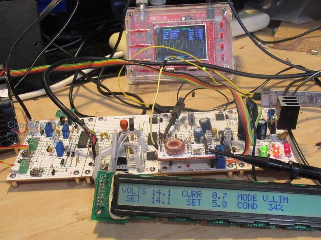 Following photo shows the SCR heatsink (which replaced the two power diodes) & the control pots. 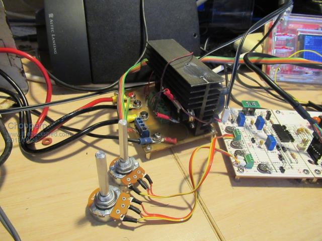 Next is the rear end of the old charger itself. An aluminium panel with the original diodes on it was removed & the shunt resistor & cut-out mounting rearranged a bit as was some of the wiring. 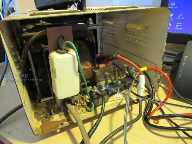 Next is screen photo of BitScope display showing the 100Hz trigger/sync pulses (yellow) & the 'OneShot' pulse ouputs (Green). The 100Hz pulses trigger the 'OneShot' pulses (RH edge). The 25kHz SCR trigger pulses are gated by this +ve pulse. This in turn determines the output. To the right is the one second data output to the terminal. 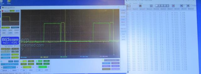 The following photo shows the output ripple (AC) on the DSO & LCD display at 20A O/P. It operating flat out with both the volts & current outputs below the set values. 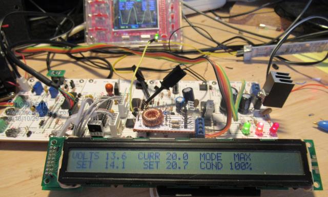 Test Battery 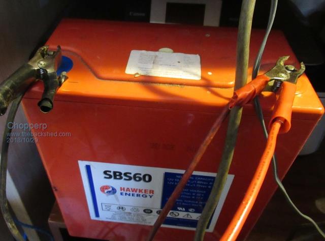 Dummy Load 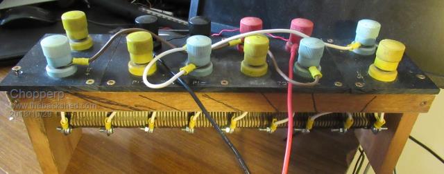 2018-10-29_101331_Battery_Charger_12V.pdf 2018-10-29_103242_Battery_Charger_12V_Basic.pdf I've moved on to testing the circuit on a 36V phase controlled charger but managed to blow up one of its SCR's. More to follow when I get around to fixing it. I will endeavor to get back to the 12V unit later BTW, I copied & pasted this post as I went into Wordpad. Came in handy as I accidentally deleted most of the stuff but that was probably due to me NOT deselecting the stuff before I added something else. (cont - z may have also worked) TBC ChopperP |
||||
Revlac Guru Joined: 31/12/2016 Location: AustraliaPosts: 1026 |
That is looking good Brian  Its seems quite similar to the Ericsson (Telecom) Battery chargers I'm using, Only have one working control card at the moment all old components and could well give up soon, Its 50 Amp 48 Volt Did give it a run about a week ago for half an hour at 11:30PM just give the lithium battery bank a little tickle up, didn't really need it but keep them happy. Perhaps I should have another look at the control cards again and adapt a few ideas. I may have a picture of the choke and capacitor arrangement after the SCR's If i can find it. Cheers Aaron Off The Grid |
||||
Chopperp Guru Joined: 03/01/2018 Location: AustraliaPosts: 1057 |
Hi Revlac / Aaron Thanks. Still a fair way to go. Fairly big charger you have there.  Some photos would be interesting thanks. Brian ChopperP |
||||
Revlac Guru Joined: 31/12/2016 Location: AustraliaPosts: 1026 |
Ok After some issues with my old image scanner, hopefully it is legible, if not perhaps the zip is better? Mostly the top quarter is of interest 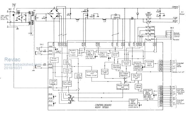 I also have a 20Amp Ericsson battery charger, the circuit is a little more simple compared to the 50amp version. all of them have 2 output chokes 1 small other large. Trying 1 of the 2 chokes on the inverter see how they go. I haven't had a real good look yet, but I think the circuit you have could run these as well with a bit work figuring it all out. 2018-10-31_220655_50amp_Ericsson.zip Cheers Aaron Off The Grid |
||||
Chopperp Guru Joined: 03/01/2018 Location: AustraliaPosts: 1057 |
Hi Aaron Thanks for that. ChopperP |
||||