|

|
Forum Index : Electronics : Grid tie inverter battery charging
| Author | Message | ||||
| Tinker Guru Joined: 07/11/2007 Location: AustraliaPosts: 1904 |
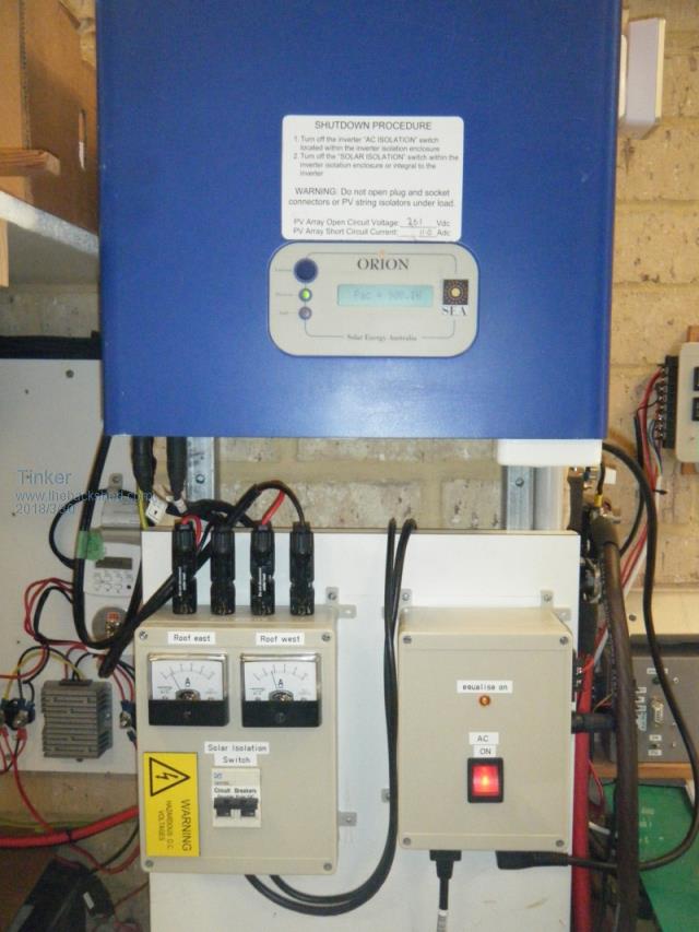
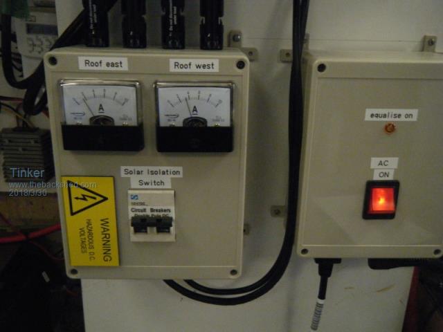
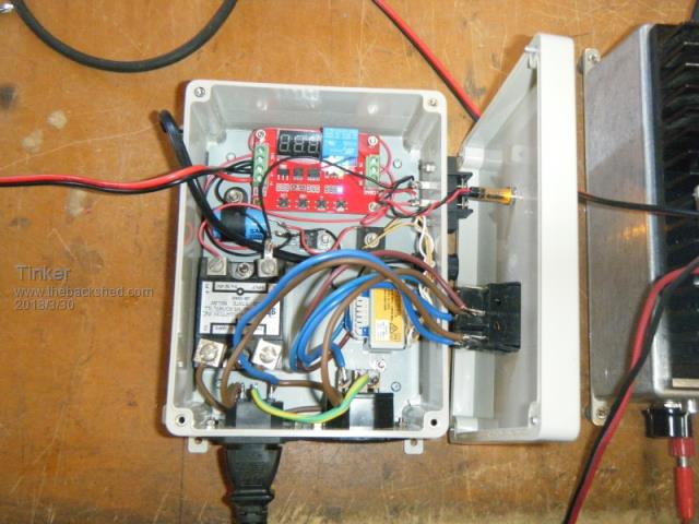
At last everything was installed and connected so I could try that connecting a small grid tie inverter to my LF *big* inverter idea. Well, it worked first go - sort of  . .Here is a pic of the installation:  And a close up of the control boxes:  On the left is my version of DC isolator. There are two strings (1000w each) of panels on the roof, one facing east and the other facing west. While the panels within a string were identical, each string uses a different panel technology. Hence my running down two separate feed cables to analog Amp meters. As the panels almost never see equal sunshine I can see on the Amp meters what is coming in. There are 1000V/16A diodes in that box, to combine the two strings into one. They eliminate any possible back-feeding due different output voltages. Explanation: My other 5 strings of 48v panels are similarly connected to one Outback controller. I have noticed that with low light some of the 5 (one each string) Amp meters were reading backward. Fitting isolation diodes eliminated that. I used 30A Schottky diodes for that, they were good for 150V. These diodes, TO 220 case, need to be on a decent heatsink BTW. On the right is my AC isolator, a pic of its inside below:  It contains the DVB01 voltage controlled relay, turning the AC connection of the Orion inverter on or off. This is the "bang bang" method as oztules so quaintly puts it  but its perfectly adequate for this supplementary charging requirement. but its perfectly adequate for this supplementary charging requirement.I set the relay to 'grid tie' to the big LF inverter when the battery falls below 53.5V and disconnect above 54.0V battery voltage. My lithium battery bank changes terminal voltage relatively slowly so I added a 10 sec relay delay at turn on to prevent it chattering. The AC side was switched with that SSR (more about that later) and a little transformer & rectifier, providing the 12V control voltage, completes the box internals. Anyway, I switched the AC on to the 2KW Orion inverter, after closing the DC isolator, and everything worked as expected. The inverter did its count down thing and connected to 'grid', charge was flowing into my battery - great. So I was surprised when I disconnected the LF inverter load, allowing the battery voltage to raise. The SSR turned the AC off as expected at 54V battery but then the Orion inverter made a horrible buzzing noise. Not good. Checking the cause I saw lots of nasty spikes on my little waveform monitoring oscilloscope, which made the penny drop  . One SSR switches only one side of the AC, I needed to isolate *both* sides. . One SSR switches only one side of the AC, I needed to isolate *both* sides.Fortunately I had another SSR and room (just) in the box to piggy back it. That fixed the buzzing, it looked a goer now. More testing, by cycling the battery voltage up and down and checking the operation of my 'bang bang' box followed. On one test I let the battery voltage drop lower, to about 52V when the grid tie inverter indicated a fault. "GFCI Failure" shown on the screen and nothing working. That fault code is not on the manual list for codes, anybody knows what it means? The manual says to reset the unit turn off the DC isolator, which I did. Re connecting this switch made everything work again as expected. So, now I will let it run overnight and see if in the morning, when the batteries are low (usually around 75%)the grid tie kicks in to provide a boost from the East facing panels before the sun shines on my 3KW north facing panels and turns the grid tie charging off. Out of curiosity, somebody might answer this: I notice when the grid tie inverter is pumping out charge, its AC being connected to one of the LF inverter GPO's, the power meter on the inverter shows it as 'outgoing' power. I suppose that device cannot distinguish in which direction power flows through the little CT coil. Am I right? Klaus |
||||
Madness Guru Joined: 08/10/2011 Location: AustraliaPosts: 2498 |
Klaus I think you will find you will make more power if you get a GTI with 2 inputs and separate MPPT's. When that one set was pulling the meter backwards it would still be able to make power at a different voltage level. Secondhand GTI's are cheap and they have inbuilt amp meters also. There are bi-directional power meters that sense which way the current is flowing. They will show if you are exporting power to your inverter or consuming power from it. These Eastron Meters are popular, they have a wide range and not all are bidirectional, I gave the 220 MODBUS version they are around $30 with post from China. There are only 10 types of people in the world: those who understand binary, and those who don't. |
||||
| Clockmanfr Guru Joined: 23/10/2015 Location: FrancePosts: 429 |
Good to see another 'bang bang' switch off/on with a voltage comparator to shut down the AC side. I will watch your progress with interest. Everything is possible, just give me time. 3 HughP's 3.7m Wind T's (14 years). 5kW PV on 3 Trackers, (10 yrs). 21kW PV AC coupled SH GTI's. OzInverter created Grid. 1300ah 48v. |
||||
| Warpspeed Guru Joined: 09/08/2007 Location: AustraliaPosts: 4406 |
A super neat and very well thought out installation Klaus, as usual... I suppose a grid tie inverter does not normally "import" power in its normal original designed mode of operation, so its probably not sensitive to the complete phase reversal of the current now being measured. Probably just a CT and a bridge rectifier to measure current, so it does not care which way the current is flowing with respect to the voltage. Cheers, Tony. |
||||
Madness Guru Joined: 08/10/2011 Location: AustraliaPosts: 2498 |
The GTI is working as it normally does so nothing is different there. The AC current at the off-grid inverter can flow either way. A basic current meter will not tell you whether you are drawing power from your battery via the inverter or charging the battery. There are only 10 types of people in the world: those who understand binary, and those who don't. |
||||
| Tinker Guru Joined: 07/11/2007 Location: AustraliaPosts: 1904 |
Yes, Gary, I have digital Amp meter on a shunt from the battery. I was just surprised seeing the charging registering on my output KWh meter. A favor please, that little grid tie inverter does not like something with my earth connections. Says something like excessive ground current and shuts down fairly regularly when starting up and the thing is testing itself. If I reset it it will charge as expected but does that earth fault thing again after full battery shut down. Could you tell me exactly how the earths are connected at your set up? Earth connection to your big two stack inverter? Earth connection to your grid tie inverter? House earth? Thanks in advance. Klaus |
||||
Madness Guru Joined: 08/10/2011 Location: AustraliaPosts: 2498 |
Hi Klaus, My GTI's will not operate if there is less than 1 Mohm resistance to ground in the panel circuit. So the dc PV panel circuit must be isolated. Panels can sometimes get water in them which makes them useless with a GTI. The case of my off-grid inverter is connected to ground and there are MOVs between both the negative and positive sides of the power board and the case. Battery Negative is connected to ground. There is one earth stake for all the AC electrical in the house and this is bonded to the neutral in the switchboard. There must be only one connection between neutral and ground. The case of the GTI is also connected to ground like any earthed electrical appliance. There are only 10 types of people in the world: those who understand binary, and those who don't. |
||||
| Tinker Guru Joined: 07/11/2007 Location: AustraliaPosts: 1904 |
Thanks Gary, Hmmm, that's interesting. Nothing DC in my inverters or battery is earthed. I earthed the rails on the roof that mount the grid tie panels. My switch board has the usual neutral/earth connection and the earth goes from there to a ground stake. My big inverter case is earthed (via its AC output cable). The grid tie inverter is earthed via its AC connection to the off grid inverter. Can you see a problem with this? I will try to disconnect the solar panel rail earth tomorrow, perhaps these second hand panels do leak to the frame a little. Klaus |
||||
Madness Guru Joined: 08/10/2011 Location: AustraliaPosts: 2498 |
The problem could be in the panels or the inverter itself may have a problem, are there any hazy areas in the panels? There are only 10 types of people in the world: those who understand binary, and those who don't. |
||||
| Tinker Guru Joined: 07/11/2007 Location: AustraliaPosts: 1904 |
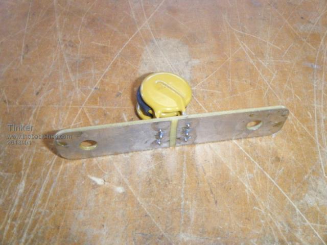
Thanks for that tip Gary, I was unaware about that solar panel 1MOhm earth resistance thing. So, I first made one of this:  Its just a bit of scrap PCB board with 3 salvaged MOV's ex Aerosharp on it. The resistance across is greater than 10M Ohm. Connected it to the panel rail earth wire, practically isolating them now from the ground stake. This did not fix the problem. So I though it must be something inside the little Orion 2KW grid tie inverter. The AC earth connection is good, even cleaned the pins of the 3 pin plug to make sure. But there was a little black wire connected to chassis earth coming out from the shrink wrapped DC panel input. The DC wiring is quite short and terminates at a barrier strip. I cut the shrink wrap off - it looked messy anyway - and found under it short metal braid sleeves over the DC wires, the braid had the thin earth wire connected to it. I removed that braid altogether, could not see much point in having 5cm of braid over high voltage DC wires. Now it appears to behave, the intermittent 'ground fault' message is gone and it syncs as expected. I will let it run by itself under voltage sensing control for a while now, hopefully its fixed. Thanks again for your suggestions. Klaus |
||||
| Tinker Guru Joined: 07/11/2007 Location: AustraliaPosts: 1904 |
So, my 'bang, bang' method of grid tie inverter connection to stand alone inverter has been doing its thing trouble free now for a week or so. Each morning it connects to provide extra boost charging from my East facing panels and when the LYP battery bank reaches the pre set 54.7V it turns off. Usually for the rest of the day as the 3KW north facing panels cover all my daytime power demand easily. Setting that DVB01 voltage sensing relay with its Chinglish instructions was a pain every time I did a little adjustment to its settings. So I drew a flow chart of the instruction which I attach below, in case somebody else finds this type of instructions more useful. Not every function is listed but, with the help of the manual, these should be easier to decipher.  If anybody spots an error in that chart please let me know and I will correct it. Those relays are brilliant, especially the 0.1V setting resolution. Klaus |
||||
| Clockmanfr Guru Joined: 23/10/2015 Location: FrancePosts: 429 |
Excellent 'Tinker'. Voltage comparator DVB01. I do like simplicity with my OzInverter projects. Most folk on here are wizz kids with the electronic stuff, but yes, explaining and following a simple straightforward procedure is Something ordinary assemblers of the OzInverter will require in the future. Yes, your 10 seconds time delay is in the correct ball park. Everything is possible, just give me time. 3 HughP's 3.7m Wind T's (14 years). 5kW PV on 3 Trackers, (10 yrs). 21kW PV AC coupled SH GTI's. OzInverter created Grid. 1300ah 48v. |
||||