| Author |
Message |
tzitzu
Newbie

Joined: 30/01/2018
Location: United KingdomPosts: 4 |
| Posted: 07:53pm 27 Feb 2018 |
 Copy link to clipboard Copy link to clipboard |
 Print this post |
|
Good evening everyone! 
I'm new to the forum and even newer in this(off-grid solar inverter)and because I stomp at the transformer size/power I thought is better to ask for help.
To put a a month story short, I got across a toroidal transformer rated at 2.5 KVA,
which had to unwind it and rewind it properly to suit the need of an inverter. problem is similar to those I've read in this forum ( no info's about the core specs).
I've tried usual formulas, with approximation or suggested values for magnetic fields etc., and everything turn out different or confusing(for me) values related.
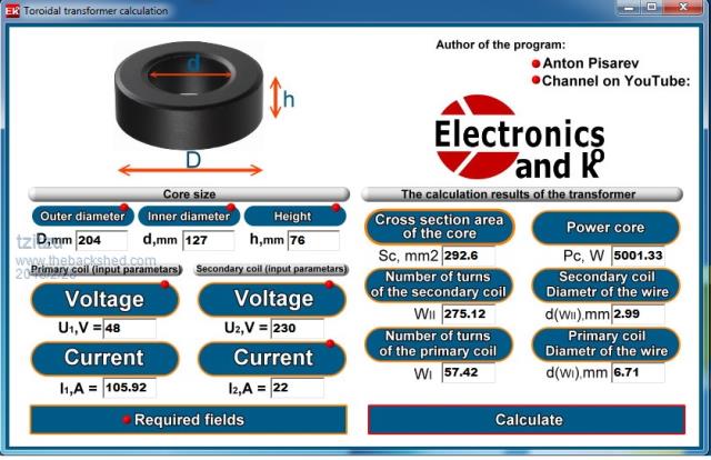
Recently I've found a program to calculate a toroidal transformer but putting values aside formulas, there's like 120 turns difference for secondary.
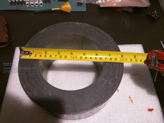
the core itself is D-204mm, d-127mm, H-76mm

the values I got for the turns would be:

calculating magnetic flux using those values, is 1.2740 Tesla, if I modify it from 58 to 70 turns it goes lower to 1.0556
is it a good idea?
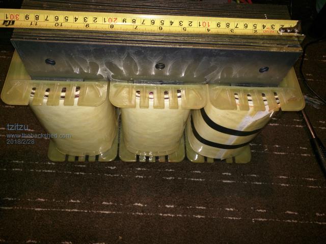
and in case it helps for further opinions, I got a supposed new transformer which is now pieces for wires purpose 3 and 4mm wires 
.

My biggest question and help that I need, are those values correct?
Of course any opinion and suggestions are more than welcome.
Thank you.
Edited by tzitzu 2018-03-01 |
| |
Madness

Guru

Joined: 08/10/2011
Location: AustraliaPosts: 2498 |
| Posted: 08:43pm 27 Feb 2018 |
 Copy link to clipboard Copy link to clipboard |
 Print this post |
|
Those figures for the secondary of the Toroid look about right. If your inverter is based on an EG8010 chip you need to change the primary voltage to 26V even though you have 49V battery bank. Output power is going to e more like 2.5KW continuos, it would and 5KW as shown in that calculator for a few minutes.
There are only 10 types of people in the world: those who understand binary, and those who don't. |
| |
tzitzu
Newbie

Joined: 30/01/2018
Location: United KingdomPosts: 4 |
| Posted: 09:18pm 27 Feb 2018 |
 Copy link to clipboard Copy link to clipboard |
 Print this post |
|
Thank you Madness!
Yes you are right, inverter board will be based on EG8010 board with IR2113S as drivers.
May I ask why to lower voltage on the primary?
is there any chance to keep it close to 5kw? |
| |
Madness

Guru

Joined: 08/10/2011
Location: AustraliaPosts: 2498 |
| Posted: 10:05pm 27 Feb 2018 |
 Copy link to clipboard Copy link to clipboard |
 Print this post |
|
You need the lower voltage primary as converting DC to AC the peak 48V needs to be divided by 1.44 for the mean AC voltage which is 33VAC. It then needs additional headroom to maintain regulation under load. A 48VDC to 230VAC inverter needs a 9-1 ratio in turns and copper cross section.
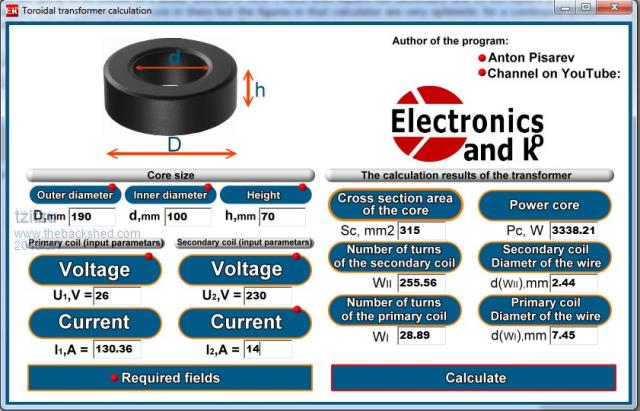
The more copper wire cross section you can fit will give you more power but there will be a limit. I have a core which is 190mm OD 100mm ID and 70mm high it will run for extended periods at 4.5KW. As the one you have has the same size hole you are going to be limited to a similar amount of wire. I have 6mm square mm secondary and 38 mm square primary. You may be able to squeeze a bit more in there but the figures in that calculator are very optimistic for a continuous power rating. I am working on real experience with my figures.Edited by Madness 2018-03-01
There are only 10 types of people in the world: those who understand binary, and those who don't. |
| |
tzitzu
Newbie

Joined: 30/01/2018
Location: United KingdomPosts: 4 |
| Posted: 07:00pm 28 Feb 2018 |
 Copy link to clipboard Copy link to clipboard |
 Print this post |
|
Thank you very much Madness,
It all makes sense now. I don't have experience on dc/ac inverters and that's a first major project ( excluding neon bulbs inverers  ) )
I still have a doubt regarding the core power since you've been kind enough and share the specs of yours, I thought to give it a try and I got this results that are quite similar with your test

Strange is that mine have less core section but longer circumference. could this be the reason?
Should I start winding it as per your specs then test a maximum load see how far it can go?
thank you.
|
| |
Madness

Guru

Joined: 08/10/2011
Location: AustraliaPosts: 2498 |
| Posted: 08:32pm 28 Feb 2018 |
 Copy link to clipboard Copy link to clipboard |
 Print this post |
|
The cross-section dictates how many turns are required, the hole determines how much wire cross section will fit.
That calculator has secondary current as a required field so whatever you enter there will affect the output. I still think that calculator is very optimistic about what power output you will get for the copper wire size. It could be that the calculator is using power ratings for an amplifier where they are looking at peak power.Edited by Madness 2018-03-02
There are only 10 types of people in the world: those who understand binary, and those who don't. |
| |
tzitzu
Newbie

Joined: 30/01/2018
Location: United KingdomPosts: 4 |
| Posted: 10:24pm 03 Mar 2018 |
 Copy link to clipboard Copy link to clipboard |
 Print this post |
|
Thank you Madness, sorry for the delay,( job takes me most of my free time)
I'll follow your advice, 2.5 should be enough for this project ( basic light and fridge for a small country side house).
I'll post later on the test results.
kind regards. |
| |
Madness

Guru

Joined: 08/10/2011
Location: AustraliaPosts: 2498 |
| Posted: 11:57pm 03 Mar 2018 |
 Copy link to clipboard Copy link to clipboard |
 Print this post |
|
2.6 KW will do that easily, keep in mind you will have probably double that for 3 minutes or more. So if you put the jug on to boil it is not going to go up in smoke.
There are only 10 types of people in the world: those who understand binary, and those who don't. |
| |

