
|

|
Forum Index : Electronics : 2 Channel 12V Fan Controller
| Author | Message | ||||
Madness Guru Joined: 08/10/2011 Location: AustraliaPosts: 2498 |
Just finished doing an upgrade to Oztules 12V fan controller originally designed for the Ozinverter but could be used for anything needing automatic fan control. The original version only had one output, I have used one of the spare channels of the LM339 Comparator so that there are 2 separate inputs and 2 outputs. In my inverter I use one side for the Heatsinks and the other for the transformer. It all fits on a 50mm square PCB. Sensors are 10K Thermistors . 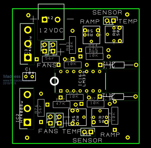 2018-01-26_105714_TempFan2_Silkscreen.pdf 2018-01-26_105740_TempFan2Copper.pdf 2018-01-26_105714_TempFan2_Silkscreen.pdf 2018-01-26_105740_TempFan2Copper.pdf 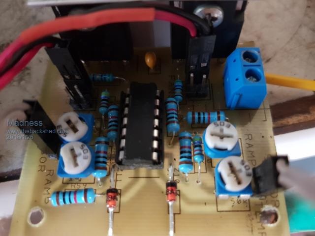 This is Oztules explanation of how it works. "It is a very simple use of a quad comparator chip I have lots of. We only use 1 in this case, and I was surprised at how well it worked... so I built some more. The comparator compares two voltages, and if the + input one is higher than the other the output transistor is turned on, if not then off. So we have an open collector output to deal with....... which means two things. 1. we need to supply it with voltage on the collector ( via 10k ) 2. when the +>- then the transistor is turned on and shorts the collector to ground.... so on is off and off is on. To see how it works, 1. we use a 10k and a 3v zener to establish a fixed reference voltage on pin 7 ( +input) This gives us a set point that we can use to compare the temp probe to. 2. We set up a voltage divider using the 47k, the 50k pot and the temp probe all seriesed with Vcc to ground.... fed to pin 6 (-input) 3. When the NTC temp goes up, it's resistance comes down, pulling the output of the 50k pot lower and lower 4. When it gets lower than pin 7 voltage, then the comparator will switch off the transistor ( which was shorted to ground when on), and the 10k pull up resistor ( Vcc to pin 1 output) will be able to deliver voltage to the now open circuit collector on pin 1... this voltage then fed to the fet to switch fan on. Now thats as a comparator, it is on or off..... if we introduce negative feedback into the - input ( pin 6) then we alter the stage gain, and the more feedack we introduce, the lower the gain, and the sharp on/ off behaviour of the comparator is made wishy washy.... thats tech talk for it will now switch on and off before and after the set point, with a voltage slope rather than hard on or off..... this translates to the fet as more or less voltage to the fan/s. The feedback is introduced at pin 6 via the 50k pot on the right. It takes some of the output through a 10k and then a 50k pot back to the input of pin 6.... so we can change how hard and fast the fans turn on. I set mine so that as it approaches the set point, the fans wake up and start rotation, silent and slow, then as the set point gets closer, they speed up, if they can stabilise it at low speed then good, else it gets hotter, the fans spin faster until you can hear them... all the way up to full on at the set point... so feedback pot for slope rate." There are only 10 types of people in the world: those who understand binary, and those who don't. |
||||
| Tinker Guru Joined: 07/11/2007 Location: AustraliaPosts: 1904 |
Nice to see you got that controller actually working. I dabbled with it a long time ago when Oztules first mentioned it (back in the PJ conversion days) but never got it running satisfactorily. My fan growled fearfully at low speed and was very iffy as to when to start up at all. The upshot of this was I gave up with this idea altogether. There are very cheap temperature controllers on ebay, some have a nice temperature readout as well. All the ones I use work well. But the best thing one can do with these home made toroid inverters is: Put the Mosfets on a decent size heatsink in the first place. Put it in a decent size box. It not hard to make one. Trying to shoehorn it into an aerosharp box might work in a cold climate but it gets quickly frustrating if anything in there requires changing. I found by doing both of the above, the 3 fans virtually never come on in the first place, so running them at low speed makes no sense. Today I ran another test after changing the internal (heatsink) fan control from the 8010 output to a small ebay controller. Its set to come on at 40 degrees big heatsink temperature. The separate two 80mm exhaust fan controller senses the small (hot) heatsink temperature. Ambient in the shed was 30 degrees. Load was 5500W It took almost 15 minutes before the fans came on. They managed to hold the temperature around 42 degrees inside the enclosure. The fridge was cycling on and off as well on top of the 5.5Kw load. After about 30 min I gave the batteries a rest from the 150+ amp drain. The fans then ran for a short time only before the temperature dropped below their set turn off point (I use 2 degree hysteresis). Klaus |
||||
oztules Guru Joined: 26/07/2007 Location: AustraliaPosts: 1686 |
Nice version Mad. I think Clockman does a similar thing. I just use one, for both 120mm fans. I treat the 80mm fans as toys, and won't use them in this application. They have a cross section of only 5000sqmm, and have to scream to do much good. The 120mm ones have 11000 sq mm cross section, which makes a huge difference when only idling along, they still shift an appreciable amount of air when running silent.. thats why I do it. I have not had the same experience as Tinker has, and prefer this system to any other I have had to be in close confinement with. I still think it is useful to have air flowing over the caps as much as possible. The other components are not as heat sensitive, so if I can have the caps being cooled for no noise, I think it is a useful adjunct to the design. I don't consider a bang bang approach as satisfactory, been there and done that and I don't care for it at all. I do agree that big heat sinks are a better way to go than smaller, but I still use the smaller ones as thats all they seem to need. I don't know if rf radiation is a problem coming from the heat sinks, but it may be cause concern for some folks if they are Ham radio people. The box should act as a faraday shield I guess, but don't know for sure. Maybe someone else has had a problem with RFI, but it has not surfaced here.... but may soon. There's a ham building one down the road... we'll see then I guess. Tinker "Ambient in the shed was 30 degrees. Load was 5500W It took almost 15 minutes before the fans came on. They managed to hold the temperature around 42 degrees inside the enclosure. The fridge was cycling on and off as well on top of the 5.5Kw load. After about 30 min I gave the batteries a rest from the 150+ amp drain." I'm still amazed at how well these 8010 things work... just seem to go about their business under all circumstances. I know it took a long while for you to get it working this well,but gee don't they perform without fuss. ........oztules Village idiot...or... just another hack out of his depth |
||||
Madness Guru Joined: 08/10/2011 Location: AustraliaPosts: 2498 |
Klaus I live in QLD it gets quite warm here I wish our ambient temperature was only 30 degrees ATM. Last summer my inverter was running in a shipping container where it regularly got to 45 degrees and beyond. Using the same controller as above but with Oztules original version with 4 140mm fans inside 2 Aerosharp cases. I have no problems with overheating in the inverter, the fans have never run at full speed. They make some funning sounds before starting up as they are computer fans designed to run with PWM plus to tell it what speed to run at. There is absolutely no reason I can see as to why you have any issue with this setup. Oz I am running 4 140mm fans off the board above also the Aerosharp cases are turned 90 degrees so natural convection occurs. The fans very rarely run fast enough to hear them apart from the funny noises before they get going. There is a photo of Clockmans version on his website, it is just the original circuit duplicated with 2 LM339's, as it has 3 channels not being used I thought the above version was a good idea. There are only 10 types of people in the world: those who understand binary, and those who don't. |
||||
oztules Guru Joined: 26/07/2007 Location: AustraliaPosts: 1686 |
Mad... now I'm fan jealous.  Odd thing, my fans never make any weird noises that I am aware of ......oztules Village idiot...or... just another hack out of his depth |
||||
Madness Guru Joined: 08/10/2011 Location: AustraliaPosts: 2498 |
The one I have are 4 wire fans the same as on a computer CPU cooler, they come out of some old Antminers (for mining bitcoins) I have. They are supposed to have a digital signal to tell them what speed to run at. If you supply 12V only they run flat out but at low voltages the PWM tries to simulate the sounds of old Dr Who episodes. I have other 2 wire fans that run silent but the ones I am using are high-quality ball bearing fans. I don't mind the noise it is not loud and it lets me know the cooling system is working even though the fans may not be turning. There are only 10 types of people in the world: those who understand binary, and those who don't. |
||||
| noneyabussiness Guru Joined: 31/07/2017 Location: AustraliaPosts: 513 |
http://www.anotherpower.com/board/index.php?topic=1170.0 If anyones interested, i used a arduino and a 10k thermistor... 32khz pwm (so no noise at all) and adjustable ramp up speed... the code is about halfway down page... And you can duplicate it for 2 channel (or 4 if you use another timer) No pcb, like madness though. .sorry I think it works !! |
||||
Madness Guru Joined: 08/10/2011 Location: AustraliaPosts: 2498 |
I have an Arduino version also using Dallas digital temperature sensors, records maximum temperature too so you know exactly how hot this get. The digital sensors allow you to have lots sensors on the one input pin plus give accurate actual temperature readings. The board here is Analogue, the noise is resulting from fans that are designed to controlled digitally, I could do that with an Arduino but have not bothered. The circuit here is quick and simple, works well especially for those who don't have Arduino experience. There are only 10 types of people in the world: those who understand binary, and those who don't. |
||||
| Tinker Guru Joined: 07/11/2007 Location: AustraliaPosts: 1904 |
Well, to each his/her own but I think you missed my point. What I am trying to say is that there is no need for a fan (of any size) to run (at any speed) for a lot of the time *if* due consideration was given to the size of the heat sink *and* the size of the enclosure for the inverter. Me thinks the ozinverter is on the small size on both counts. Yes, I know it works wonderfully well but it does so by having to run the fan a *lot* more than my inverter, which has a practically identical schematic but a very different physical layout. The Aerosharp box was designed for 3KW with an external heat sink. Some builders are trying to squeeze a lot more power and the heatsink for this inside the box, requiring a big fan and for it to run a lot. This could be avoided. Here is a case in point; the picture below shows the panel of my converter PJ inverter. This has a 8KW (Chinese) power module and a rewound 3KW toroid which, BTW, has a very generous copper section primary and secondary winding. But, unfortunately, I did squeeze the lot in an recycled Aerosharp enclosure. 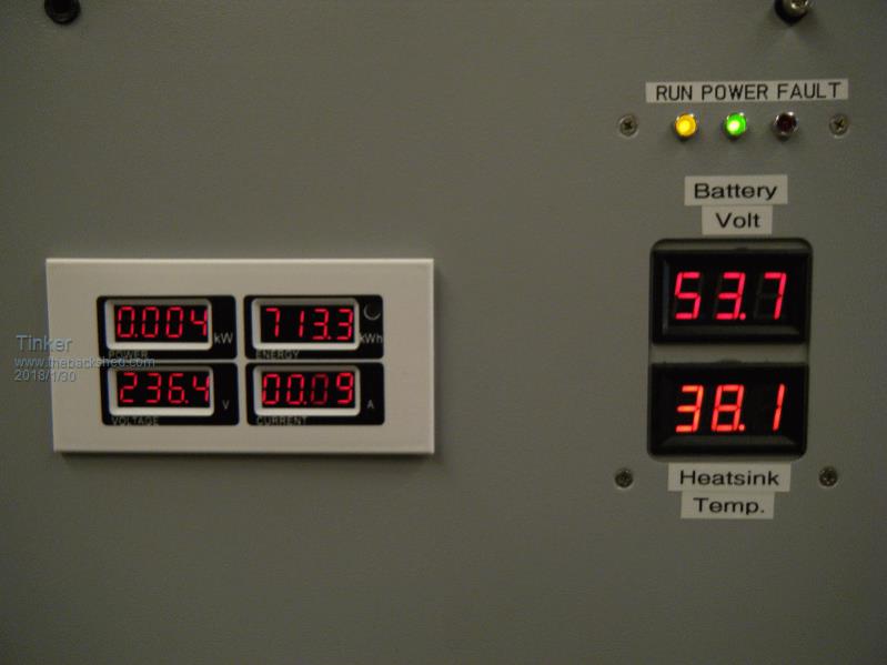 Note that there is virtually no load on, this inverter only powers the lights in my house. Yet, its 4 x 80mm fans (2 in, 2 out) have to cycle on constantly to maintain the shown temperature on this, relatively cool, 30 degree Perth summer day. And we do have our share of 40+ days here as well Madness, the fans will just about run non stop then. Next a picture of my new, own design, double stack inverter. 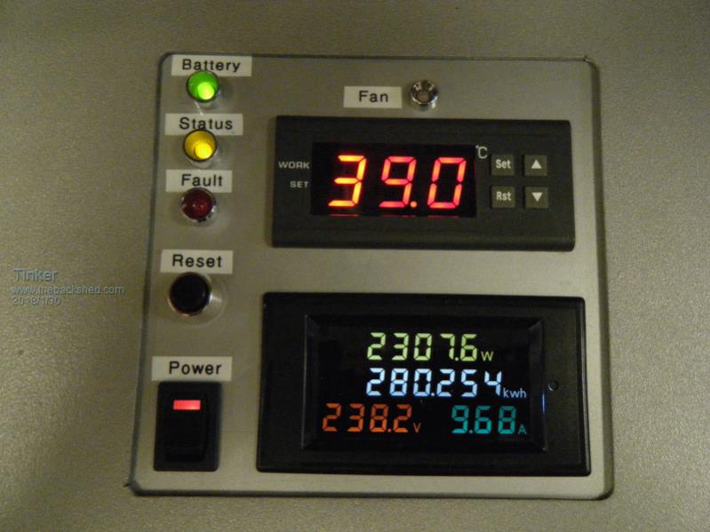 Note that this one *does* have a reasonable load on, yet its fans took 15 min or so to come on and then have long off times with that load. With no load the fan never runs at all unless the ambient gets very close to the 40 degree fan trigger temperature. I am not worried at all about the expensive capacitors getting too warm, they are located on the cool side of the PCB and do not see more than 42 degrees or so on a very hot day. So, having smaller fans that virtually need not to run at all with my usual cycling loads does not matter at all. An interesting comparison is the size of the long heat sink: Ozinverter: (source Clockman) 271 x 80 x 26mm fins. Mine: 400 x 80 x 75 mm fins Klaus |
||||
Madness Guru Joined: 08/10/2011 Location: AustraliaPosts: 2498 |
Klaus I turned the Aerosharp cases 90 degrees so the 140mm fans are on the top and bottom of the case this allows natural air flow due to convection. My fans don't spend much time running, they only kick in when the inverter is running around 3.5KW and beyond. However my heatsinks are quite a bit bigger than Oztules, the natural air flow and bigger size means the toroid fans run much more than those on the PCB side. Keep in mind too that originally those Aerosharps had zero air flow inside as they need to be watertight hanging of an external wall of a house. Since I started using a GTI the off grid inverter has it quite easy as the GTI is making 3-4.5KW. During the day it could be putting 4KW back through the inverter to charge batteries if there are no heavy loads on. This reduces as PWM kicks in as the batteries reach absorb voltage or if there is more loads on like AC. So the inverter I built only works hard at night as the GTI does the heavy lifting during the day. I am also about to add a second 5KW GTI but it will only have 1.5 KW of panels on it for the time being. Today was cloudy but here is the results from the GTI for the day it spent most of the afternoon doing very little as the battery was at full charge. Date: 2018-01-30 E-Today: 14.5kWh P-Peak: 3.63kW Yield: 4.79$ CO2 Avoided: 11.6kg E-Total: 1.36MWh Total Yield: 447.94$ Total CO2 Avoided: 1.09T There are only 10 types of people in the world: those who understand binary, and those who don't. |
||||
| Tinker Guru Joined: 07/11/2007 Location: AustraliaPosts: 1904 |
Mad, what puts me off those Aerosharp boxes is their odd shape with the sloped side and oversize lid. If they were a simple rectangle they would be a lot easier to use, especially if two are joined. However, the 2mm ss metal is a bitch to work, just for drilling simple holes, let alone large cutouts for fans. I'm really surprised nobody else seems to make their own box. Mine are just a top & bottom frame bent from 20x20x3mm angle iron and joined to angle iron uprights to form a suitable size box. Its very easy to fit brackets & shelves for parts to that and everything is accessible from *every* side. That makes it a breeze to extract things like the heavy toroid and leaving everything else in place, should it be necessary later for some reason. The 4 part covers are a simple 1.6mm alu plate top & bottom and identical back & side 1.6mm alu panels with one 90 deg. bend. My latest inverter (single core) is coming along fine, almost got the case finished and then its just a question of fitting all the parts into it. Klaus |
||||
Madness Guru Joined: 08/10/2011 Location: AustraliaPosts: 2498 |
There is no doubt you do an excellent job with yours Klaus. I have not found the stainless steel that hard to work with. It would do my head in to throw them away when they do a perfectly good job. There are only 10 types of people in the world: those who understand binary, and those who don't. |
||||
| Clockmanfr Guru Joined: 23/10/2015 Location: FrancePosts: 429 |
OzCooling board. 2 Fans and 2 temp sensors for the toroid, ..... and 2 fans and 2 temp sensors for the PCB's 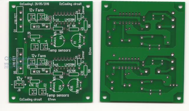 Everything is possible, just give me time. 3 HughP's 3.7m Wind T's (14 years). 5kW PV on 3 Trackers, (10 yrs). 21kW PV AC coupled SH GTI's. OzInverter created Grid. 1300ah 48v. |
||||
Madness Guru Joined: 08/10/2011 Location: AustraliaPosts: 2498 |
What I did is make better use of the IC, it has 4 channels but that circuit only uses one, my modification just eliminates the 2nd LM339. I find it works fine with single thermistors. There are only 10 types of people in the world: those who understand binary, and those who don't. |
||||