| Author |
Message |
Zibe
Newbie

Joined: 15/01/2018
Location: AustraliaPosts: 10 |
| Posted: 11:47pm 24 Jan 2018 |
 Copy link to clipboard Copy link to clipboard |
 Print this post |
|
Hi all,
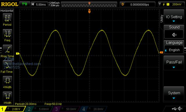
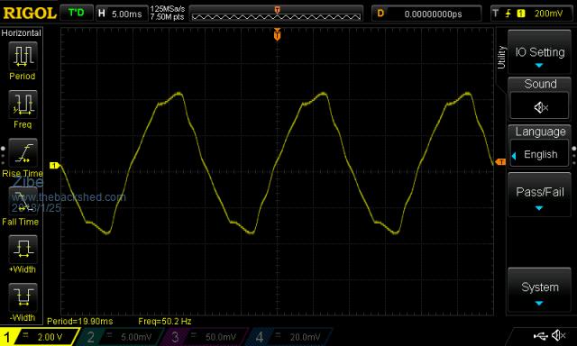
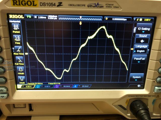
I am attempting to clean up the waveform of my SPWM inverter. Its fine when its supplying a resistive load like a light bulb, but when it drives a switch mode power supply its cutting the tops / bottoms off the wave form. I am using a traditional H-Bridge unipolar arrangement to a 150VA, EI 6V:240V transformer. The attached picture of the wave for clipping is with a single 18W compact fluorescent bulb. Data was captured on the 240V output via a 3VA isolation transformer. So far I have made the following changes / checks to no avail.
• Verified the DC bus has sufficient low ESR capacitance. I doubled it to no effect during testing.
• Changed the gate drive resistor from the MOSFET driver from 22 ohm to 7.6 ohm (lowest resistance to stay within the gate drive specs at 12V).
• Changed the dead band to approx. 200uS.
• Added additional capacitance to the output using X2 capacitors (found adding 2uF of X2 caps to slightly clean up non peaks regions of the wave).
• Tested with a few inductors on the input to the transformer. My thought that this is not needed so much due to it being a EI core transformer and being reasonably lossy.
• I have reasonably sized cables from the batteries to PCB and to the transformer. I am using 4 * IRFB4110. Supply is a 5S4P arrangement, 21V – 17V (lithium 18650 batteries).
I am looking for suggestions etc. on reducing the clipping for switching loads etc.
Thanks
|
| |
Madness

Guru

Joined: 08/10/2011
Location: AustraliaPosts: 2498 |
| Posted: 12:03am 25 Jan 2018 |
 Copy link to clipboard Copy link to clipboard |
 Print this post |
|
Do you need some extra turns on the primary or more capacitance? I get a similar effect if I run a board to test it with no capacitors.
Inductors and different dead band time effect the waveform at 0 crossing in my experience, your issue is at the peak.Edited by Madness 2018-01-26
There are only 10 types of people in the world: those who understand binary, and those who don't. |
| |
Zibe
Newbie

Joined: 15/01/2018
Location: AustraliaPosts: 10 |
| Posted: 01:01am 25 Jan 2018 |
 Copy link to clipboard Copy link to clipboard |
 Print this post |
|
When you say extra turn on the primary I assume you mean in parallel to reduce voltage drop? I have a little over 10,000uF capacitance on the DC Bus so i am thinking that should be sufficient for the 18W Compact Fluro. I measure very little ripple on the DC bus.
A separate question, does the EG8010 do pulse by pulse error correction of the output voltage wave form?
Thanks |
| |
Madness

Guru

Joined: 08/10/2011
Location: AustraliaPosts: 2498 |
| Posted: 01:43am 25 Jan 2018 |
 Copy link to clipboard Copy link to clipboard |
 Print this post |
|
No I mean more turns to get it to a higher voltage, if you disconnect the transformer from the inverter and apply 240V to the secondary you should get 26V on the primary if it is a 48V Inverter. In the Oziinverters we have 6 10,000 UF capacitors.
As far as I am aware the 8010 corrects the voltage for each full cycle of the 50HZ output.
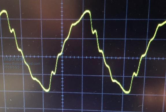
I know compact fluros can cause very bad distortion on a small inverter. Sorry I missed that part of your first post, so it may not be your inverter that is at fault. Someone sent me the image below recently, this was caused by compact fluro lights on a small inverter with just 4 MOSFETs. Without the CF's it gives a perfect waveform.
Edited by Madness 2018-01-26
There are only 10 types of people in the world: those who understand binary, and those who don't. |
| |
Tinker

Guru

Joined: 07/11/2007
Location: AustraliaPosts: 1904 |
| Posted: 09:24am 25 Jan 2018 |
 Copy link to clipboard Copy link to clipboard |
 Print this post |
|
If you are checking an inverter waveform by looking at its reduced voltage level from a step down isolation transformer keep in mind that the transformer itself introduces a distortion. Its not perfect!
I made a resistive voltage divider to monitor the AC voltage directly (you *must* use a ground isolated CRO for this) and compared this waveform with one via a step down isolation transformer. They were markedly different. No load BTW.
Klaus |
| |
Zibe
Newbie

Joined: 15/01/2018
Location: AustraliaPosts: 10 |
| Posted: 12:53am 02 Feb 2018 |
 Copy link to clipboard Copy link to clipboard |
 Print this post |
|
I haven’t had much time to test using resistors as I am away at the moment. The more the waveform distorted, the louder the hum of the transformer was. One thing I am thinking about is a possible error in my circuit / code (running on an ATMegga).
I am using the HIP4082 H-bridge driver, it’s a pretty handy IC and has built in deadband control and shoot through control. I am using only two of the control pins for the low side control (in this configurations the high sides output is a negation of the low side) as per the following example from the datasheet and timing diagram.
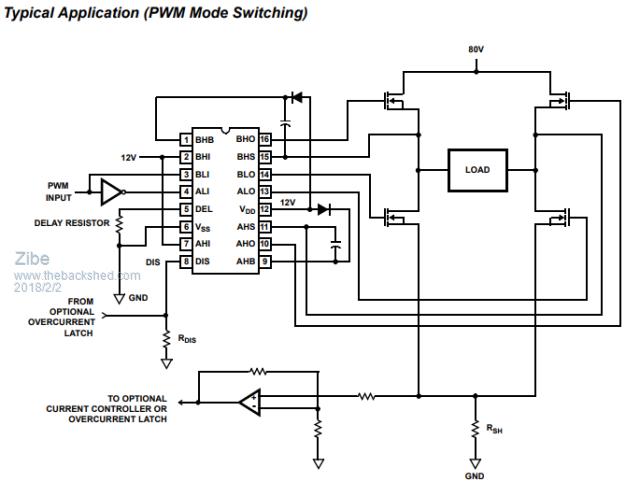

So either the low or the high mosfet of one side of the H-Bridge is on/off at any one time, never floating unless during the dead time. So during the on part of the PWM, everything is normal but when off it is suddenly reversed polarity (rather than floating). Both sides of the transformer would be held to the positive rails for example.
Really I just need to double check my understanding is correct.
I did have a brief play with adding capacitance to the output which smoothed out the waveform somewhat but the voltage peak was still lagging compared to a symmetrical wave form.
Thanks for your help.
|
| |
Zibe
Newbie

Joined: 15/01/2018
Location: AustraliaPosts: 10 |
| Posted: 01:24am 09 Feb 2018 |
 Copy link to clipboard Copy link to clipboard |
 Print this post |
|
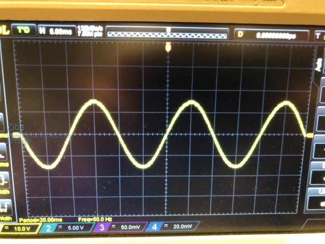
As an update and for anyone who comes across this issue. I tested another inverter I made that uses a Latronics PVE1200 transformer. It too was experiencing the significantly distorted wave form. I found that using the inductor in series with the transformer was creating the issue (I think it was around 1.1mH from memory). When I removed it from the circuit there isn't any viable distortion to the waveform when switching on multiple Compact Fluorescent Lights.
My thoughts are the inductor was preventing sufficient current to the transformer directly affecting voltage stability. The inductance being too large for this application.
Likewise my 150VA EI transformer might be too lossy (sag) to adequately drive switch mode supplies as I do not use an inductor but experience a distorted voltage wave form especially where current is drawn at the voltage peaks.
With Inductor (used a current limited & rampped voltage supply to soft start).
Without Inductor.
|
| |

