| Author |
Message |
ryanm
Senior Member

Joined: 25/09/2015
Location: AustraliaPosts: 202 |
| Posted: 01:25am 11 Jan 2018 |
 Copy link to clipboard Copy link to clipboard |
 Print this post |
|
Hi Guys,
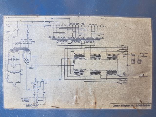
I've got a large three phase arc welder that's been saved from landfill. Works OK except I can't get it to reduce the DC voltage from maximum. The potentiometer behind the voltage knob looks OK with a meter. I was wondering if anyone here might have some idea of where I should start troubleshooting. I've attached a photo of the wiring diagram. I know a fair bit about DC circuits, but once there's coils and multiple phases getting around I'm a little out of my comfort zone.
Any advice would be very much appreciated.
Ryan.

Edited by ryanm 2018-01-12 |
| |
Madness

Guru

Joined: 08/10/2011
Location: AustraliaPosts: 2498 |
| Posted: 05:41am 11 Jan 2018 |
 Copy link to clipboard Copy link to clipboard |
 Print this post |
|
Arc welders control current not voltage.
There are only 10 types of people in the world: those who understand binary, and those who don't. |
| |
rustyrod

Senior Member

Joined: 08/11/2014
Location: AustraliaPosts: 121 |
| Posted: 06:14am 11 Jan 2018 |
 Copy link to clipboard Copy link to clipboard |
 Print this post |
|
The input at the top L - L - L will go to a big switch indicated by the links between windings,
This switch should control the amps
I am not a welder fixer, only observing the circuit pictured.
The voltage pot, I am not sure how that would control the voltage, but MAY control a wire feed ?.
The associated transformer (left side) and pot with bridge rectifier seems small to provide any substantial DC voltage superimposed on the main output
Being DC output I suspect there may be another wire feed box.
Perhaps a model and a pic will help us to help you
........................................................................
I am in the midst of rescuing a big welder too, the wire-feed box is faulty or not getting any power from the big box and like you I am a tad nervous of poking around in there as I do not have a circuit.
I have a smaller mig stuck on flat out but I can adjust the wire feed,
Maybe one day I will pull it to pieces and fix it, I don't want to rush it.
cheers rustyrodEdited by rustyrod 2018-01-12
Always Thinking |
| |
ryanm
Senior Member

Joined: 25/09/2015
Location: AustraliaPosts: 202 |
| Posted: 06:42am 11 Jan 2018 |
 Copy link to clipboard Copy link to clipboard |
 Print this post |
|
No wire feed as it's an arc welder not a mig.
It definitely controls the voltage on the output between about 18-58V OC as I've got a slightly newer functional unit at the shop as well. I figure it controls the voltage as a method of controlling the current. I assume the current limiting method used in smaller welders might not work as well at higher currents (it's rated at 650 amps) because it doesn't have a control for current, just output voltage.
Have to find my alligator multimeter probes so I can live test it without killing myself I think. |
| |
dwyer
Guru

Joined: 19/09/2005
Location: AustraliaPosts: 574 |
| Posted: 08:11am 11 Jan 2018 |
 Copy link to clipboard Copy link to clipboard |
 Print this post |
|
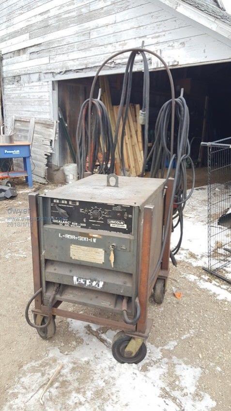
Is that what you talking about this old Lincoln welder

Cheers Dwyer
|
| |
rustyrod

Senior Member

Joined: 08/11/2014
Location: AustraliaPosts: 121 |
| Posted: 09:10am 11 Jan 2018 |
 Copy link to clipboard Copy link to clipboard |
 Print this post |
|
Ok, let us analyse the circuit some more
The big lower right tranny is a choke, with a set of winding making a complete circuit in the middle, across a ??? then one wire to the wiper of a (?preset?)pot across the bridge rectifier,
The other wire passes to the wiper of another pot switched internally or externally and back to across the bridge rectifier,
Why? what is the theory?
A - increasing dc in the inner coils ?increases the output
B - or ? decreases the output
So if no voltage in bridge rectifier is that flat out ?
The multi-meter is the way to go for some testing
Maybe a google search 'How does a x?x?x welder work' may shed some ideas
cheers rustyrod
Always Thinking |
| |
Revlac

Guru

Joined: 31/12/2016
Location: AustraliaPosts: 1026 |
| Posted: 01:02pm 11 Jan 2018 |
 Copy link to clipboard Copy link to clipboard |
 Print this post |
|
http://www.lincolnelectric.com/assets/servicenavigator-public/lincoln3/im409.pdf
Page 26. May be helpful
Just looked again, that might not be correct.  Edited by Revlac 2018-01-12 Edited by Revlac 2018-01-12
Cheers Aaron
Off The Grid |
| |
ryanm
Senior Member

Joined: 25/09/2015
Location: AustraliaPosts: 202 |
| Posted: 01:15pm 11 Jan 2018 |
 Copy link to clipboard Copy link to clipboard |
 Print this post |
|
50% correct dwyer. Definitely old, but it's a Miller not a Lincoln. hehe
Thanks for the help, but I think I should poke around with my meter a bit in the morning more before troubling you guys further.
Ryan. |
| |
Pete Locke
Senior Member

Joined: 26/06/2013
Location: New ZealandPosts: 181 |
| Posted: 11:16am 12 Jan 2018 |
 Copy link to clipboard Copy link to clipboard |
 Print this post |
|
Aaah. One of the old school new welders of the day, but still old. It's quite simple, and probably the reason you found it in transition on its way to the big hole in the ground. A delta secondary is fed through what used to be a single choke after the rectifier, with a pull out bar to regulate the welding current. Cheaper ones had a pull bar in the main transformer. If you are built like Hercules these things were easy to cart about :-) The choke that the transformer feeds (from a long ago memory) is a single transformer looking thing. They came up with the DC bias creating flux/anti magnetism/anti induction...various manufacturers called it different things to make it easy with a 'Knob' rather than the big heavy pull bar. The volt meter is there as a sales gimmick of the time, and pretty much told you it was live. The reason you can't regulate it, it the choke will have a shorted turn/turns, negating any DC control that might have once been. If as the circuit indicates there are six chokes, it will be one or more that have shorted. Three phase indicates it was built for heavy use. If they are individual, bypass one at a time to see if things start to work again. When you find the dead one, good luck finding a replacement. You may have a re winding job on you hand :-)
The principle of the regulation is about the same as the old bobbin voltage regulators that early cars used. But it will still be great for fast and furious welding. Just get the thickest rods you can find :-)
Cheers
Pete'.Edited by Pete Locke 2018-01-13 |
| |

