
|

|
Forum Index : Windmills : furling actuator
| Page 1 of 2 |
|||||
| Author | Message | ||||
| kitestrings Senior Member Joined: 23/04/2014 Location: United StatesPosts: 102 |
I thought folks might be interested to see our latest turbine addition. I added a linear actuator (well hidden behind all the weatherization efforts) which operates off the CC to furl the tail. This is not for normal running mode operation, but is set up to (softly) shutdown the system when the input voltage to the controller goes over a preset voltage, currently about 125V. So if a windy overcast day turns sunny, and we no longer need the power. It has a built-in potentiometer so the presets can be set, and triggered with one contact closure using one of the auxiliary relays. So far working pretty well. We'll see if it holds up thru all the different weather expectations. ~ks |
||||
| jorn Newbie Joined: 30/12/2012 Location: NetherlandsPosts: 22 |
Kitestrings, Next step is pitchcontrol? http://www.fieldlines.com/index.php/topic,145925.594.html Rgds. Jorn |
||||
| kitestrings Senior Member Joined: 23/04/2014 Location: United StatesPosts: 102 |
jorn, No, I don't think so. That's a thread that has goes back ~2011 or '12 IIRC. They've done some creative stuff; midwoud1 & mbouwer, and I've enjoyed watching their progress. To me, I like the simplicity of a furling tail design. I've run with this design now for over 30-yrs. I like that I have basically three moving parts up in the air, and all of the electronics and most of complexity are not 85' in the air. My furling actuator can, and may fail - it is really just pulling a rope - but the turbine will still furl, all on its own. ~ks |
||||
| Warpspeed Guru Joined: 09/08/2007 Location: AustraliaPosts: 4406 |
Is that an electric automotive power steering rack ? Cheers, Tony. |
||||
| kitestrings Senior Member Joined: 23/04/2014 Location: United StatesPosts: 102 |
Wrspd, No, it is a 12V (electro-mechanical) linear actuator. I took two rubber steering stabilizer boots and joined them with a piece of PVC to enclose the arm. The unique thing with this one is that it has a built in potentiometer, so you can set up to three preset positions. And, it has an auto-return feature which allows you to go to one position when the "ignition" wire is energized, and return to a second when the signal is removed. This is ideal in our case. It allows the furled, unfurled positions to be programmed and controlled with a single dry-contact operation. ~ks |
||||
fillm Guru Joined: 10/02/2007 Location: AustraliaPosts: 730 |
As Always , nice work KS and the actuator with some easily settable stop points is handy if you just want a partial furl. I am a big advocate for manual furl and fit it standard to the OZ Wind Turbines. With me it is more born out of necessity with the power the GOE222 blades develop and back when I thought AXFX Alts were so to say " The Bees Knees"and I burnt up a few before adding it to the last one I built that now sits on a shelf marked with 'one day'a Var Pitch set.... when time permits. I have had customers set up similar to what you have but more actuated / triggered on Wind speed and when using very large Dia GOE blade set. But I mostly recommend a simple correct sized weight hung on the cord or sliding down a star picket that does not allow the tail to return to the lower stop when the tail starts furling, it may take a few gusts to get it to the point where it goes over center. With a pin in the picket holes to stop it where required, this then gives a bit of movement on the tail to dampen any the side gusts. Being able to safely park a turbine in any wind is paramount in my books and manual furl has been around 200years on pumpers so its a tried and proven method. PhillM ...Oz Wind Engineering..Wind Turbine Kits 500W - 5000W ~ F&P Dual Kits ~ GOE222Blades- Voltage Control Parts ------- Tower kits |
||||
| kitestrings Senior Member Joined: 23/04/2014 Location: United StatesPosts: 102 |
Thanks fillm. I'm pretty partial to off-set furling, and manual furling also. It just seems to be the most passive way to stop a turbine for any reason. Some folks on OP have demonstrated a similar results with variable-pitch rotor, but it is not without complexity, and with it, the potential for failure. We actually dabbled with the idea of a ratchet on the yaw hinge that could be engaged from the ground. I had a handful of early sketches: 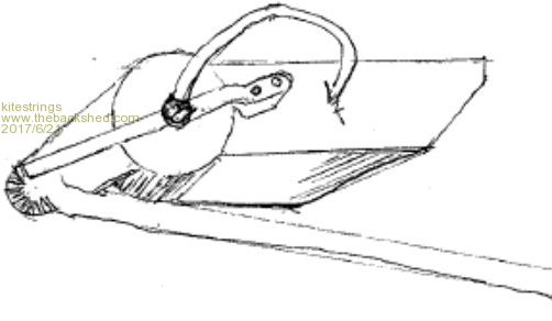 In the end I like the approach we have. I had been closing it down with a small hand winch. This just allows me to do it from the house, or PC. For a total shutdown, I furl the turbine and then connect the load bank. This brings it to a minimal rotational speed - less than 20 rpm I'd guess. With the controller it gives us the option of having it close up based on input voltage. You can set a Vhi voltage, delay (how long there before it operates), and a Vlow, or reset (also with a delay). Still, I kept the hand winch there just to be safe. Look forward to seeing more of your work. I hear great things about those GOE222 profile blades. ~ks |
||||
| kitestrings Senior Member Joined: 23/04/2014 Location: United StatesPosts: 102 |
So last night was a pretty good test. Pretty high winds. I'd been in and out of the house watching things. I decided to try intentionally lower the trigger point to simulate a shut-down. I dropped the set-point to just above the input voltage I'd been seeing; ~95V IIRC. True to from it tripped the actuator, furled the machine, and I watched the output drop from about 1,500-1,800 watts to maybe 200 watts within a half-minute or so. I then dropped in the load bank and the rotor dropped from 60-65 to about 20 rpm. Hopefully it works when it is -10 F and snowing this winter. That will be the real test. ~ks |
||||
| flc1 Senior Member Joined: 20/11/2011 Location: New ZealandPosts: 242 |
Gday Kitestrings,That looks to be a good system you have there. I will also be useing a 12volt dc , voltage activated actuator for my system,but setup a diffrent way, looking at your system has given me the idea to put the actuator up on the turbine itself,and run a couple of small feed cable up the centre of the pole or bleed off some power up there to operate it,,it could also furl itself in high winds without the actuator,,,,the actuator would simply push against a set point on the tail to furl it,with out being conected to the tail. The actuator I have is only about 120mm long with a thrust force of 900n (90kg) and a lock force of 2300n,and draws about 4 amps under max load, a slightly larger actuator than mine,with say 300mm stroke and same thrust power should do it. Can easily enclose the actuator from the weather. bugger!! I wish I had seen this post before I had started my rebuild .  I guess I could still change things on my turbine as its still in the shed at the moment. I guess I could still change things on my turbine as its still in the shed at the moment. |
||||
| DaveP68 Senior Member Joined: 25/11/2014 Location: New ZealandPosts: 292 |
Hi kitestrings Nice work with your automated furling actuator system. Looks like you have more than "partial furling" control demonstrated with the last test. Better than any manual system. That's a big drop from a peak of 1800 W down to 200 W and with the load bank added in down to 20 RPM. From what I know about blade TSR, the RPM even in high winds will not be able to get above 50-60 RPM. The reason for the low, but "controlled" RPM is the blades are fully stalled. This keeps everything well within safe operating limits too. You've forced the blades into a 'power coefficient' of less than 10 % of their optimum operating range which would normally extract the maximum amount of power. Here's a 'tip speed ratio vs power coefficient' graph to illustrate what I mean, more for those that read this that may not understand what I'm referring too. 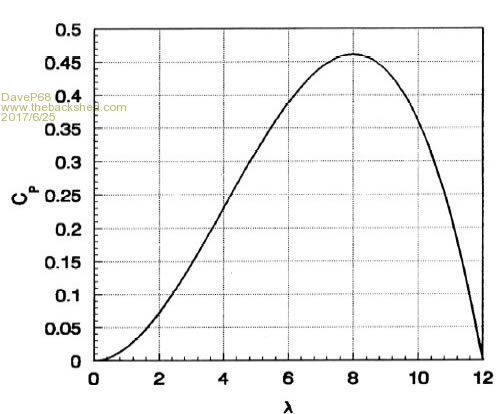 By the way have you seen my topic on Electronic Dynamic Braking? There are realities if you do not accept, will lead to frustration because you will be spending time on wrong assumptions and the results cannot follow! The Dunning Kruger Effect :) |
||||
| kitestrings Senior Member Joined: 23/04/2014 Location: United StatesPosts: 102 |
I suspect it would be an interesting engineering study to model the effect on the airfoil as a turbine furls. Furling seems really simple and yet is probably one of the least (well) understood topics. This site has IMO one of the better illustrations that I’ve seen: http://www.thebackshed.com/windmill/Docs/Furling.asp Still, the insert pictures might be a bit confusing to someone who’s never seen this (or that you’re trying to explain it too). Notice how all three show a perfectly round rotor path. So this is actually viewed from changing vantage point; one where you stay perpendicular to the plane of the blades. In practice, there is an initial period, when the winds are light, where the tail does not leave its resting position against the lower stop. Gravity keeps it there, and there is simply a playful “teetor-tooter” balance between the thrust on the rotor and tail’s natural tendency to stay parallel to the wind stream. Most builders have the tail open a little (5-15 degrees) past the 90-degree mark so that at, or near, cut-in the turbine is at a starting position that is perpendicular to the wind. As the wind increases of course the tail comes off this lower stop. The plane of the blades now transitions from a circle as “seen” by the wind to an ellipse. As the wind gets higher still, the area of the rotor becomes an ever decreasing ellipse; to the point where the plane of the blades and the tail are effectively in the same path. Where the blades stall along this progression might be challenging to calculate given the variables at work, but as DaveP suggests, I assume it happens if we have a workable design. Even when you watch this is real time – it’s fascinating IMO – what you see, and what it appears that you see are at times at odds. It often looks as though the tail is the only thing that is wagging about. I liken it to watching a stage coach wheel that appears on film to be turning backwards ;>]. |
||||
| DaveP68 Senior Member Joined: 25/11/2014 Location: New ZealandPosts: 292 |
Hi Kitestrings This is how I see what you were trying to explain about how the "front on swept area" of the blades actually looks during furling as explained above. No furling full swept area of blades.  Now 50 % furling with blades at 45 deg to the flow of the air stream.  Now 75 % furling with blades at 67.5 deg to the flow of the air stream.  This along with an offset angle of attack of blades to the wind flow is the reason for the big drop in power in the shaft feeding the PMA. A much easier way to keep things under control like you have outlined above. Well done and thanks again for your valued contribution to adding to the knowledge on this website. There are realities if you do not accept, will lead to frustration because you will be spending time on wrong assumptions and the results cannot follow! The Dunning Kruger Effect :) |
||||
| kitestrings Senior Member Joined: 23/04/2014 Location: United StatesPosts: 102 |
A couple minor tweaks to this thing: Since it looks to be a more permanent feature now, I ran some non-metallic PVC liquid-tie and buried a portion of the run where we have a logging access road. 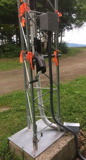 I documented a make-shift schematic for when ICRS in the near future. 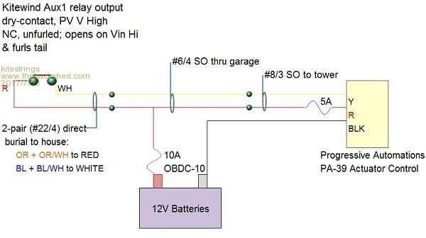 Lastly, I'm adding a constant voltage pump/motor driver on the line to the tower. This thing runs off a small 12V bank in the garage. We have our (trusty) old Trace inverter there which runs the OH door openers and a few light loads. When the batteries dip what's left on the end of the run to tower is another ~1/2V lower. The pump driver will provide a steady ~14V output with a varying input (11-15V).  |
||||
| kitestrings Senior Member Joined: 23/04/2014 Location: United StatesPosts: 102 |
Notice the "Rutland" turbine on the cupola. I call this our functionalweather vane. It charges, a bit, into the 12V bank in the garage. |
||||
| flc1 Senior Member Joined: 20/11/2011 Location: New ZealandPosts: 242 |
looks good ks,maybe an idea to put a couple of concrete posts or large wooden posts either side of your tower so some clown doesn't take out your tower with their car/truck. |
||||
| kitestrings Senior Member Joined: 23/04/2014 Location: United StatesPosts: 102 |
That'd be me in this case. The tower is just off my driveway, and I'm the 'plow guy'. Seriously, this is something I've been thinking about. It'd be pretty easy to back into it in the winter especially...or the LPG guy... I'm thinking to just drag a couple of big rocks over on each side of it. It's all ledge there. |
||||
| flc1 Senior Member Joined: 20/11/2011 Location: New ZealandPosts: 242 |
Yep. That would do it.big tower like that would come down hard. |
||||
| kitestrings Senior Member Joined: 23/04/2014 Location: United StatesPosts: 102 |
I've added this constant voltage converter. It is a pretty slick unit. Takes a varying input voltage 11-15V, (5A max.) and allows you to set the output voltage. Here I have the thing powered off my truck battery, and I'm setting the output voltage to about 15V. 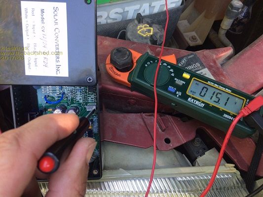 Current losses have been causing me a bit of grief, so I plan to move the DC source closer to the thing. I also found a aux. battery isolator, so I should be able to isolate power to this thing on a cell that is unaffected by [other] load. Should of probably done this in the first place. ~ks |
||||
| kitestrings Senior Member Joined: 23/04/2014 Location: United StatesPosts: 102 |
I was reminded that I probably should update this post. Our final schematic has changed a bit. We added another battery closer to the actuator (but still inside the shop), and I also put a diode/isolator in to block this battery from any local loads. The actuator uses a built-in potentiometer, and the controller is a bit sensitive to current losses. Seems to be working well now. 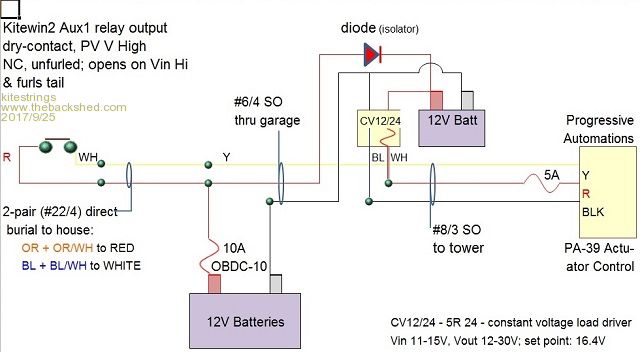 |
||||
| flc1 Senior Member Joined: 20/11/2011 Location: New ZealandPosts: 242 |
Gday Ks Good looking setup you have there,and it works well which is the main objective. Hopefully when I get back the auto furling switch from Dave I will be worry free during a storm aswell. Our switch was not working exactly as we would like,most of the time it worked fine, but Dave rekons hes sorted it, the problem was a tiny piece of solder in the wrong spot. |
||||
| Page 1 of 2 |
|||||