
|

|
Forum Index : Windmills : The Capacitor Doubler and Wind Turbines
| Author | Message | ||||
fillm Guru Joined: 10/02/2007 Location: AustraliaPosts: 730 |
Just to add to a bit more to what has been put up recently and to give you a bit of history on the Cap Doubler Firstly and solely it was Gordons Brainchild and was not just “Illustrated By” but put forward by him , he and myself tested these extensively in various forms years back on lathe testing and with data logging in real world. These days he is no longer on the forum to add his wisdom so all I can add is what I know, what was done then and the experience I have with them . The original thread “Visual Effect of Capacitors Link “has been locked so it cannot be added to , it has some in depth stuff if you wnt to troll through the 33 pages but in reality it really comes down to the more capacitance the more it will load. Unintentionally it became a very good form of MPPT at Low to mid wind speeds. Gordon who also designed his own MPPT Buck / Boost solely for wind at the same time that worked in real time stated there was minimal difference between the 2 . Link to some testing done back then Link - The original “Cap Doubler “was intended to fill in the void of the power curve where there “Was no power Available” . Mainly for the light to medium winds were most small wind turbines operate 99% of the time . So improving power production is a benefit but at a cost. Where it evolved to be was that you can re-wire or wind for low Resistance. Example “ a stator / rotor for its intended Voltage cuts in @ 200Rpm @ 24V or 48V rather than using more copper to get lower cut-in ads resistance that limits operation in higher winds, so by using the AC coupling of the Cap Doubler we can can be extract power at around 100Rpm and up to 200Rpm where then current will then pass through the main rectifier and doubler circuit combined . I will add we did tests with Tripler’s / Quadrooplers , and some one else up to 10 times if you think of a word for that . But at the end of the day the to get the maximum bang for your buck then the doubler is it , we found to really make the tripplers add anything was another complete st of Caps so 12 + 18 is a high cost for just milliamps of benefit. There is another use where a stator that has a very low cut in can just be AC coupled to the rectifier through the capacitors and the capacitance will reduce load and allow it it operate ( example a 48V as a 12V wit a cut in of below 60RPM ) This is a good fix for VAWTs as they stall easy and produce very little. • Numbers quoted with 200rpm / 100rpm in reality unless you set up good amp meters on doubler and main rec the actual first cut in operation cannot of the doubler can not be fully evaluated . Usually around 90% of cutin will see a gauge move As for the capacitors for a normal F&P and a Black both will react fairly well with 680uF 230V or higher DC Caps . In total 12 DC Caps are required to make a doubler The illustration below is how to correctly configure the DC Caps , by putting them bac to back -++- or +--+ in this configuration turns them into an ac capacitor , The Capacitance Value will be ½ that of what is on the individual Cap , so if we have a 680uF 230V then it becomes 340uF 230V when reconfigured to AC Coupled . Higher voltage caps must be used that will clearly give a margin of safety if the mill becomes unloaded. People have used little uF / voltage caps and wonder why it doesn’t work. 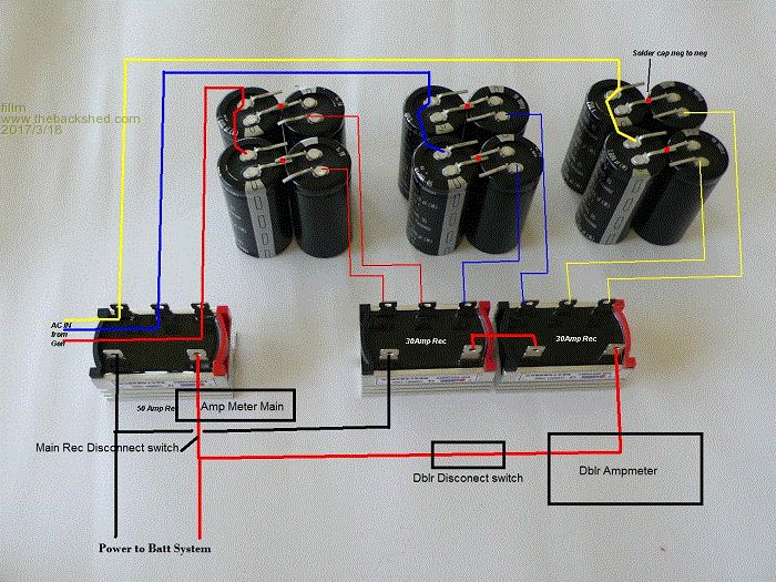 Yes , 48V it works better but 24V is easily done .as well . I mostly use 1600uF 250V Caps back to back so 800uF , this works very well with Huayas / Exmorks , First winds …. as they all have around a 200 Rpm Cut in , they also work well with the F&P ( Correctly rewired again around 180 -230) , AXFX . Again to emphasize that its original use was solely for low medium wind where a balance of lower resistance windings and the Cap Dblr gave very good over all performance and . There not really the need to try and extract maximum the power from the alternator with over size capacitors that would be out of this world in price . Below is a good example of what the doubler can do , the red trace line is on the right logger is a 2kw Huaya with the 3.1M GOE222 . It can be clearly seen the curve up to the point where the main rectifier starts at normal cut in. What it also shows is a complete shift in the power curve. These are 1600uf and the blades are still kept in a good operating range. The Left is the identical with std 3.2M Fiberglass blades , putting a doubler of this capacity on this would be detrimental. 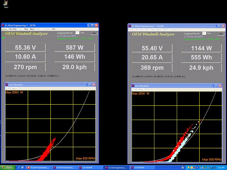 As I have pointed out before, if the blades can give power and you don’t over load them it can work perfectly . BUT also what gets given in better low wind also limits high wind performance, that can also be seen above. I have done some retesting on my test bench recently to see what the Black Cap rotor , these were done up to 960RPM on a few different configurations 6x2P 4x3P and even 12x 1pole and as Dave has stated there is an increase in power over a 100S , Yes there is but it definitely does not rule out 42poles as a waste of time . If set up correctly as a dual both will perform the same I given the same blades and matched winding resistance. The black will output more in higher wind speed. In reality with a F&P dual powered with the GOE with black rotors or 42 pole at over 2.8m Blade and not severely over loaded there is no problem with outputting very good power and with the right combination of I can easily see 1.5 kw @ a 48V system and a bit lower for 24V AT Rpms in excess of 800Rpm . If you have ever been close to one doing that it’s a scary site. When I get time I will put all the graphs along with the efficiency torque curve that gives the correct input power. As A bit of an add in - I have been putting together various forms of DC Engine powered Generators. One version is F&P based with a Dual black 12 x 1 Delta and is capable of 2.2kw but at 1300 – 1400 Rpm and is one of the options I am looking at designing for fast charge on lithium. Its up and running in a basic testing form at present and would sit all day at this level. I also have it in my head for a Slave Dual of the main that easily attaches to go to up 4.5kW. So yes the Black rotors can push so extra power but I think its more in the line of 30% tops over 42Pole .8 and 1mm. As I have said I have done a fair bit of testing and will publish it as time permits. Below is a pic of a RPM & Wind speed monitor that Pete is the brains behind. It can also switch a relay at a given RPM but he modified the program to be NC until a set RPM. Here I was playing with turning the doubler off at X rpm and this allows a bit better upper output. That’s as far as it got and lives under a bench. 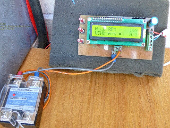 In real world it comes down to simple and effective matching of blade power to the alternator, chasing the “ IT Can Do XXXXX Watts “ is good to say but in reality count the number of times your wind turbine is sitting at that level . Although some do have serious wind lucky in some ways but it can be tiring I am told, but generally if you have a steady 15 ~20klm Average you have a good site. Below is a complete Capacitor Doubler I have done for some in the past, re-badged as the “Capacitor Power Maximizer “ and it has all contained in and gauges on both . The doubler can be turned off just to show it works. 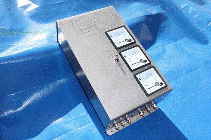 IMO , Capacitors and other forms of improving performance ,star delta switching , higher voltage MPPT… etc Axial Flux is for certain types a hobby / enthusiast and if you want to do it that’s your choice . But if you want to use capacitors then I hope this has helped and to make it work better. I do have some stock of the 1600uF Caps and they are more than sufficient for most applications and are a bit more on budget , contact me if interested. Forget it if you are using PVC pipe blades, it will stall . PhillM ...Oz Wind Engineering..Wind Turbine Kits 500W - 5000W ~ F&P Dual Kits ~ GOE222Blades- Voltage Control Parts ------- Tower kits |
||||
| KennyG Newbie Joined: 06/03/2017 Location: United StatesPosts: 12 |
Great research and info. Just what I was looking for . Thanks much ! KennyG |
||||
| DaveP68 Senior Member Joined: 25/11/2014 Location: New ZealandPosts: 292 |
Hi Phil Good plug for your tried and true Capacitor Doubler setup that has stood the test of time on the wind turbines built to date. You certainly, thanks to Gordon's circuit design got onto a winner. The "Capacitor Doubler" does a great job by acting as a 'Load Adaptive Impedance Matching' circuit to a loads like a battery, as per what Gordon discovered. He also stated that they were a good substitute to using complex MPPT buck converters etc. The way I use Gordon's 'Capacitor Doubler' circuit is by correctly matching the capacitor reactance values with the impedance of the stator. In doing so I've been able to extract 1.4 W per RPM in the 300 to 500 RPM range. Example 700 W output at 500 RPM, I've never seen any data/results get to that power output from a single stator of this website. Stator impedance is derived by know the original Star resistance between phases, which for a 36 pole copper is 32 ohms. If a change to Delta is done, then divide 32 by 3 and the new impedance will be 10.7 ohms before any rewiring is done. Then every time the stator is re wired you square the number of times "it is cut" i.e. "2"x 6p will be divided again by 4 or "3"x 4c will be divided by 9 or "4"x 3p divide by 16 or "6"x 2p divide by 36 and last "12"x 1p is divide by 144! Once the stator impedance is know then the capacitor value is derived from a formula of Xc=1/(2xPIxFxC), but this needs to be rearranged to derive the value of C. Wc=capacitor reactance in ohms PI=as you will know 3.141592654 F=frequency of the stator output i.e. 24Hz per 60 RPM so 500 RPM is 200 Hz C=Capacitor value in Farads For a working example, take a 36 pole copper stator re wired as 4x 3p Delta with black rotor cap. By using a 6x 800 uF AC value capacitors in the doubler circuit will provide about 530W power output at 380 RPM. That's into a 48 VDC battery system supplying 59 VDC at 9 A. You're also still very loyal to early version 42 pole 100s plus 80s stators which will soon be in short supply, due to average age of the product they were made for is now about 22 years! I've never said that the 42 pole stators are waste of time, so not sure how you got that impression? Did say I wasn't going to do any more testing on them as found their limits and just prefer using the 36 pole copper. As you will already know I service the very F&P washing machine all these stators come from and below is a graph of numbers of machines I've seen over 9 years (rolling annual total) as per each version made. You must have a big stash of the 100s, as I haven't seen one of those Phase 1 machines for 2 years. The 80s (Phase 2-4) are still around in good numbers as per the graph 12% of total units I've serviced in the last year. 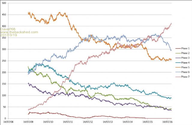 The Phase 7 machines that have the 36 pole copper stator account for 35% (Have removed Phase 8 + Phase 9's models from graph as they have Aluminium stators which are of no use). My advise is to start switching over to using 36 pole copper stators, as you are going to be forced to sooner or later. You state that you 'think' the difference between the 36 & 42 pole stators is 30% tops? Be very interested to see your actual test results i.e. Volts/Current at what RPM etc? Also Have you put up a Dual 36 pole copper with Black rotor caps of on a Turbine and measured the power output difference with your current 42 pole Dual setup? I would have expected you to have built a 36 pole Dual with Black rotor caps, as you are a "Guru" on wind turbines and have all the instrumentation to verify the results. My test results show into the "same load" a 36 pole copper stator with a black rotor cap will produce 40% more power than a 42 pole stator over the same RPM range (60 to 1155 RPM). Refer to the graph below showing difference in performance between the 36 and 42 pole stators.  Correct load matching is critical for any of these F&P stators (36 or 42) and if not done correctly will result in a reduced output power. I understand this fact better than anyone else on this website, as know some of engineers that designed the original smart drive product. You have a load match problem here. What were the Volt/Amps at 1300 - 1400 RPM to get 2.2 kW? Try a Dual 36 pole 6x 2p Delta Black Rotor cap into the same load at 1300 - 1400 RPM and you will get more power output, of at least 2.8 kW. Check out the following link of a micro hydro system using Four 36 pole stators with Black rotor caps each running around 1600 RPM producing 2 kW per unit with total combined output of 8 kW. That is 1.2 W per RPM, so they are all correctly load matched into the two Solar MPPT Grid Tie Inverters in my opinion.. 8 kW powerspout micro hydro system by TAS Energy & Heating The 36 pole copper stator with a black rotor cap from my point of view is the gift that keeps on giving  Cheers David There are realities if you do not accept, will lead to frustration because you will be spending time on wrong assumptions and the results cannot follow! The Dunning Kruger Effect :) |
||||
fillm Guru Joined: 10/02/2007 Location: AustraliaPosts: 730 |
Dave , I started this thread to put across, what has been done what was found to be a good combination of using the Cap Doubler to benefit low wind medium wind performance. If you think that its just a plug then thats your opinion if you have a problem with it then take it up with the administrator . All the info was given exactly how to set it up which some struggle with. Its all there in picture form along with info on some good cap sizes to use that are not going to cost $100 a capacitor . The last Cap Doubler I built for a customer was 2 or so years ago and over the last 10years I think all up 3 were made like that one .....The sales graph would be a dismal site compared the enlightening service records you shared from your business but somewhat irrelevant to the topic. Anyway if the black rotor 36 pole can be shown to output 2 kw or show graphs of it running into a resistor allowing the voltage/ current to match the ? Ohm resistor. And in that condition it outperform the best 42 pole by 40%, fair enough that is your opinion and it probably is a fact. Something that you over look is given 2 F&P duals ( OZ Wind of course … “Plug “ one 36 black rotor and one 42 with closely matched stator configurations to within 50RPM of each other for cut in . Then with identical blades ( GOE222 OZ Wind of course “Plug” ) .Placed side by side in average winds 15 - 25klm they will both almost the same W/hrs of “ ACCUMULATED POWER “ In this wind range, and being that as an average where most people who have a wind turbine, you could put 10 different turbines F&P, LG , Huayas whatever all roughly at the same rated kW and roughly the same cut in +-50, all with the GOE blades same Dia. I would put money on it that if they were all logged at the end of a 7 day period they would all be within 5% , why … because that is is all the blades can extract. If there was a marked difference then it would be because of a physical design being markedly better or worse than others . The loggers I use record peaks, they would all be different for the varying wind gusts differing PMAs reaction, but a 1 sec peak can not do much to the average power accumulated. There would be different power Rpm / power curves but the GOEs just move up or down in RPM to input Torque because there is no more power to be extracted for the limit of the blade . Then there is the section of wind & Rpms under normal cut-in ( make power where before their was none & only if the blades and support the load) This was the original design intention , If you can perfectly match the capacitance to the PMA and blades it will add some power through the doubler circuit and as frequency voltage increases the capacitors reach their limit and then the current starts goes through the main rectifier . It has allowed the stator to be rewired / wound at a lower resistance which does enhance the mid range . You must have the perfect calculator to find perfect sweet spot and the Std capacitance Calculation to my knowledge and is also Gordon's Its not very relevant unless you adopt a percentage of derived value as a starting point. It does not and can not take into account blade types. As for the caps I use, it's because I know that the GOE blades can support the extra load and I would think 1600uF ( 800AC ) is the upper limit unless of course on a bigger machine . Example - I have one customer with a 3 kw Huaya with a 4.2mtr Var Pitch blade set and can easily make power in the wind speed under cut, this is where the cap doubler can help and is going trial series parallel of the 1600uf caps that effectively is 1600uF/Ac. Because of its lower frequency it may be able to support more. For the std formula you used Link Here is a easy link if any one wants to go on that path Link Here If the same calculation came to work out the advice you gave plus the “ Rearranged Value “makes me wonder how you came up with 10000uF I would also think the capacitors life would be very short lived if they are taking constant high current given the ideal location What is the point of putting a tripler on a 6x2p rewire and then because the normal cutin is over 500rpm just to try and shift the whole power curve to – 300 rpm for 500W when you could probably just do a 3x4P or 4x3P, then maybe there would not have the problem excessively high loading. In all the testing you have been quoting you have never stated what size capacitors you are using and outlined the test or showed any pictures of the set up so it can be replicated. I do not have to, I can predict virtually exactly what will happen and its explained above in detail. With the test bench I have now I can test what the output will be, then as there will always be GOE Blades on my turbines and I have enough data and knowledge to know what will be a problem with loading . What would happen with different blades like tapered twisted blades, first output will be far less but with some turbines this can help with longevity. That is why you can’t put GOEs on AX-FX alts unless it Var Pitch. Even then AXFX still burn disintegrate and suffer from the resign and magnet degrading in the weather. I do not dispute the black Rotor in winds over 8m/s it will outperform a 80S /42 pole or 100S /42 pole , does it mean through all your 42 poles in the bin…No If you want to see the BIG Numbers then standing near a 3mtr turbine doing 500rpm is a “Holy Hell” 750Rpm …. People usually back away 900 … Its run for cover . The only time I have seen the 1000+ was when one of my mills became unloaded in high winds and there’s nothing you can do but watch if you don’t have a a safe protection designed in ...Manual Furl or brake . That’s why I fit M/F as std on all my turbines. F&P do not need it if you build them strong enough. So the test was a 100S ( Std ) power @ 300Rpm , I expect 48V. By my tests a std 100s can do that in star with-out a tripler as seen in the bottom graph and a doubler would make delta look better . This is a clear cut good example of what it best use would be. Allowing a stator significantly out of low / mid wind range Cut In to make power where it couldn't. 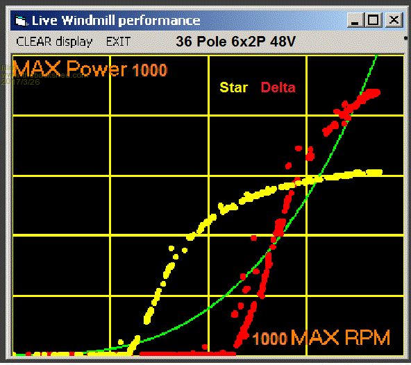 Here’s one of many test’s, this is the 36pole copper at probably 54-55V into Lithium Batts. Yes they can deliver more at the top end but as shown here its barely 20% over a similar impedance in a 100S. At the upper RPM the 100S is at 850W and the Black 36 at 950W, at that given point its probably 12% and its not going to change with higher RPM as both are reaching saturation. And given the 100s has a slightly lower cutin would help as a good candidate for a doubler. I have stated before a 80S and a 100S as a dual is a great combination. The main problem is 100S are rare now but an 80S can be set up to almost be the same . I do not test into factitious dummy loads but more where the reality of normal simple battery systems operate. 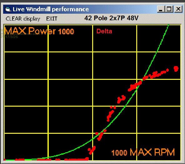 I also do not dispute that in an ideal situation the the 36 pole Black Rotor can deliver over 1kW but again its not going to happen as a std stator due to the fact its .6 wire. This then calls for your so called "Cuts" or Re-Wires as we know them over here in Aussie Land. 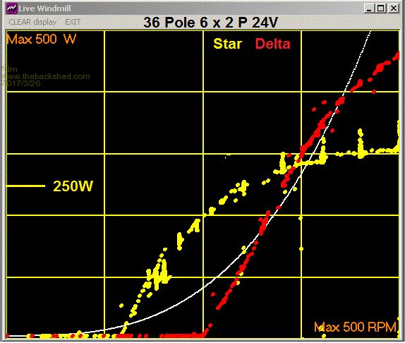 * The above graph is in 500W / 500Rpm Scale , also the risers in the yellow is the voltage difference in the dump as th@ 24V is on a small LA Batt Set . Again this would give a good result with a doubler as a dual for 24V ( dual Delta = Doublers ) and can easily get to over 800W @ 500Rpm. Even better would be one star and one delta no doublers required , this would give a good over all performer. 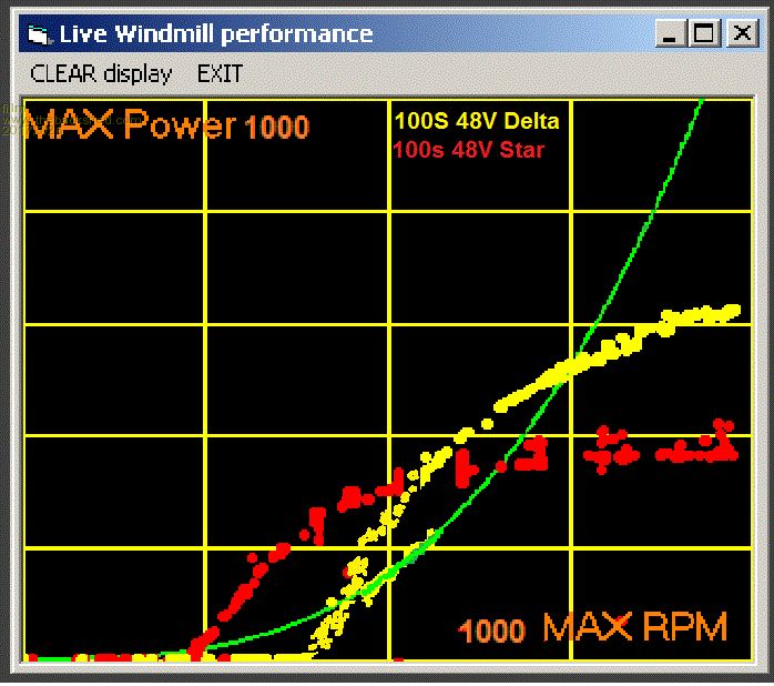 Above would be the a good ideal solution for a 100S Std in Delta and if the correct capacitance was used you would get close to what is shown below in the green fill in , this would give " Power where before there was none " and not cause excessive loading. I take it you meant the facts about the F&P , its a big claim but I see you edited this one from your original reply I hardly build F&Ps any more and have never claimed to be a "Guru" . If its the Guru status that is given near the avatar then its not given on what you know, it is only a measure of the number of posts a person has done. First this is a Engine Powered DC Charger and as a dual output is 1.1kw per stator. Usually it does not need explaining, the Volts and Amps @ 48V /55V is a simple calculation. There is no load mismatch it is as like the Ecco Hydro, the power input is predictable, Rpms can be matched with pulleys and I am pretty happy with that. I will add that I doubt there is a 42 pole that can match this but the 100s or 80s would be around 1800W . I would calculate the power difference to be 20% which falls in line with the difference from copper to aluminium. I would not even try 6x2Pole as it would be impossible to output any where near what 12x1P Delta does @ 1400 Rpm. This is reducing impedance by 1/2 again and gives the combined wire size of 3.39mm^ per phase . Yes you can have it all running at a higher voltage and then into a MPPT or Power Jack or to a grid inverter that then feeds back into an off-grid inverter or grid tie inverter. Generally quite confusing but can be done and yes probably with good results . But in reality it crosses into an area where it should only be done by licensed electrician and with approved products if you are grid feed or even off- grid. I take you do know the AS/NZ 3000 AS/NZ4777 Standards and where it crosses to ELV. I still think if you are advising or showing people what to do it should at least be legal. It can be setup to run at a much higher voltage and get to 2.2kW, but its not going to happen as easy as that. Its not going to happen on a conventional 3mtr Dual Stator F&P wind turbine, Rpms will still be the stumbling block as there with getting to usable voltage thresh hold the turbine needs to reach to suit the MPPT whatever. So the 6x2P Delta has to get to 830rpm for 100V . This could in reality be easily over 100V be well over then the range where the power and then the reputed 2.2kW now 2.8kw, seems like a lot of untried figures that do not take into account its a .6 wire. Sure Michael Lawley / Eccoinovation can sell 2.2 kw Grid Ties running at 180Vdc and Hydro Pelton wheels have Relentless predictable Hydro Power … This example means nothing to a wind turbine and also there is no way a std stator will output 2.2kw @ 180VDC 24/7. I would think at minimum it would be 12 x 1 Delta as it could be running @ 3000Rpm . But one thing for sure is it has to maintain 12Amps or (3 x 4A) without getting hot. 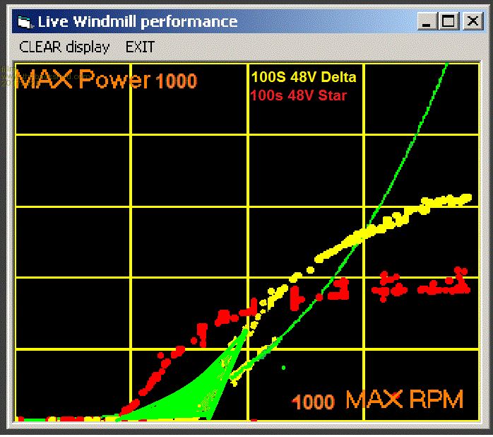 Again - The original intention of the Cap Doubler is to not overload but if you could match the correct capacitor it is one that fills in the green line on the Power / Rpm graphs I have shown above . This can also be clearly seen in the first post in the RHS logger screen . The best matched Doubler will at the point where the "Actual Cutin" is reached sees the capacitor also reaches its maximum power it can absorb from the stator then power can only go via the main rectifier. People have always tried to read far to much into this simple form of creating a better over all power curve that can also be taken to the extreme. The Cap Doubler - its just the gift of power where there was none  PhillM ...Oz Wind Engineering..Wind Turbine Kits 500W - 5000W ~ F&P Dual Kits ~ GOE222Blades- Voltage Control Parts ------- Tower kits |
||||
| DaveP68 Senior Member Joined: 25/11/2014 Location: New ZealandPosts: 292 |
Phill Why I put the graph of number of machines serviced on the post is very relevant to the topic if you are making any reference to F&P 42 pole stators. The point which you seemed to miss is that the number of 42 pole stators being available is dropping off! The 36 pole stators are now available in big numbers... The 80s stators will be in the similar limited supply situation to the 100s in the next 3 to 5 years going by that useful Graph I posted. Just because I've made some statements that the 36 pole stator can out perform a 42 pole "for the same RPM" does not imply putting 42 pole stators in the bin at all. Never said you can't use them, only making a comments re them now showing up in smaller numbers than say how many were available say 10 plus years ago. In this wind range, and being that as an average where most people who have a wind turbine, you could put 10 different turbines F&P, LG , Huayas whatever all roughly at the same rated kW and roughly the same cut in +-50, all with the GOE blades same Dia. I would put money on it that if they were all logged at the end of a 7 day period they would all be within 5% , why … because that is is all the blades can extract. If there was a marked difference then it would be because of a physical design being markedly better or worse than others . At no point did I make reference to what an F&P 36 pole copper would do compared to a 42 pole on the same set of blades side by side. All I made reference to was for the same "RPM" the 36 pole copper with black cap "correctly load matched" will give 40 % more power output than ANY 42 pole stator. If you put a 36 pole stator on a wind turbine with a larger diameter set of blades you will get more overall power output than a 42 pole. This is due to the increase in blade diameter will result in a lower RPM, as you will will know. So a 36 pole copper stator will be able to output more power (correctly load matched). The 36 pole stator set up correctly has more power output potential than any 42 pole. It's not my opinion it's just a fact. You want some values for a capacitor doubler. Again here is how it's done. Start with Stator impedance 32/3 as using Delta which gives us 10.67 ohms. Now convert what it will be when re wired to 6x 2p. That's 10.67/6^2 = 0.296 ohms Xc must be 2x stator impedance, which is 0.592 ohms Xc=1/(2xPIxFxC) 1/(2x3.141592654x168*0.0016)=0.592 So use 1600 uf AC value caps with a 36 pole copper re wired delta 6x 2p black cap. That will give an output of about 600 W @ 420 - 450 RPM into a 48 VDC battery system. Just so happens to be the very same value of 1600 uf capacitor in your "Example", so please try it out and let me know the results. Here is another calculation for the lower speed cut in stator for say 70 to 90 RPM. Set this one up as a 2x 6p Delta Black cap. Xc must be 2x stator impedance, which is now 2.67 ohms (2x 6p Delta) Xc=1/(2xPIxFxC) 1/(2x3.141592654x53*0.00056)=2.67 ohms This time capacitor value is 560 uf AC. Cut in for 48 VDC system between 70 & 86 RPM depending on battery float voltage. The Hz of 53 relates to an RPM of 133 as not to load up system at low wind speeds. Don't know why you're making reference to a capacitor tripler? I thought this subject was about "The Capacitor Doubler and Wind Turbines" bit off topic there Phill. If you want a response re the capacitor tripler, please go and post your comments that relate to that subject on that particular post. Will supply some pictures later as the post is getting a bit too long... Yes familiar AS/NZ 3000 Standards. Wasn't trying to encourage anyone to do an illegal installation. If you go back through my recent posts only make mention of 48 VDC battery systems. I only mentioned this system (which will be certified) as it is "correctly load matched" The set up of each 36 pole copper stator with black caps is around 1600 RPM (Hydro of course) wired Delta 4x 3p. Output of the best unit is 190 VDC 11.16 A so that is 2.12 kW.. I've spoken to the sparky who set the system up so info wasn't from me making some wild guess! The windings of these stators aren't getting that hot as AC circulating current per "pole" (36 in this case) is about 1.5 Amps so with 1.33 ohms resistance per pole that converts to 2W per pole and 64 W for entire stator. Won't suffer too much heat build up when one considers the total heat dissipation surface area. The rotor caps have fins on them creating enough air circulation for cooling too. Wasn't trying to mislead anyone with putting the link onto the Hydro video, as I made no reference to wind turbines in that part of the post. Thanks for posting the screen shots of your results, much appreciated. David There are realities if you do not accept, will lead to frustration because you will be spending time on wrong assumptions and the results cannot follow! The Dunning Kruger Effect :) |
||||
| DaveP68 Senior Member Joined: 25/11/2014 Location: New ZealandPosts: 292 |
Phill are you sure you haven't set up this Dual black as a 12 x 1p Star? By my calculations from all my experience of these 36 pole stators you should be getting 3.2 kW of power to fast charge your lithium batteries. 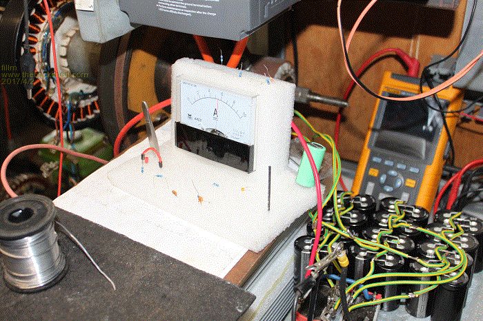 Looks to me you did the same here too, the stator in the above photo seems to be wired 6x 2p Star. That will go a long way to explain the Amp meter reading of just under 6 Amps. My set up clearly stated to use a 6x 2p Delta to get the 59 VDC at 12 Amps. My own test results from yesterday prove I was correct all along. The capacitor size didn't matter so much after all if the stator was correctly set up in the first place. Understanding these F&P stator matters if you want to get the best results from them. In case you need to see how to wire a 6x 2p Delta stator I've included a photo of how I wire mine. The colour coded wiring does make it much easier to do. There are realities if you do not accept, will lead to frustration because you will be spending time on wrong assumptions and the results cannot follow! The Dunning Kruger Effect :) |
||||
| DaveP68 Senior Member Joined: 25/11/2014 Location: New ZealandPosts: 292 |
Gordon who also designed his own MPPT Buck / Boost solely for wind at the same time that worked in real time stated there was minimal difference between the 2 . Phill would like to ask if efficiency graphs like this one were ever logged back when all the extensive testing was done on Capacitor Doublers by you and Gordon? 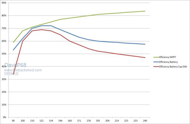 There is a problem with Buck / Boost converters if not set up correctly will take too much current from an F&P stator and limit the voltage rise to the level it needs to go to. Was it a true comparison to made between a MPPT Buck / Boost solely for wind and a capacitor doubler on 2 identical wind turbines in every other respect? Phill did you ever get around to graphing the efficiency torque curve that gives the "correct" input power? Here are 3 of mine so interested to compare what you are able to show from your test rig. 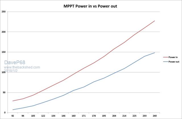 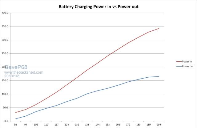 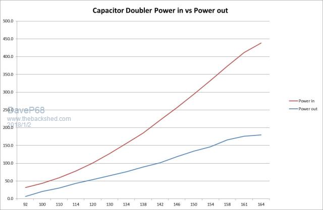 Note the worst result comes from the stator connected to a capacitor doubler! Well all I can say is with MPPT you can have the best both worlds. With an efficient power transfer over most of the operating RPM range "will" give way more accumulated power  There are realities if you do not accept, will lead to frustration because you will be spending time on wrong assumptions and the results cannot follow! The Dunning Kruger Effect :) |
||||