|

|
Forum Index : Windmills : F&P Turbine Build
| Author | Message | ||||
| fulfrog Newbie Joined: 20/01/2011 Location: New ZealandPosts: 13 |
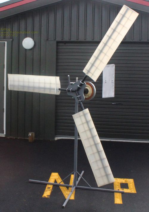
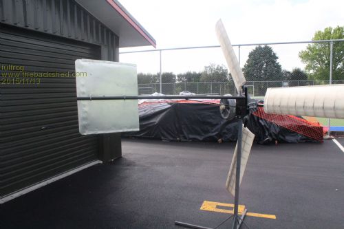
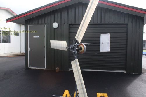
So thought I would show a few pics on my latest prototype Iíve been working on at school for my final Hard Materials project. Itís almost operational just need to add the final touches and finish the blades off and test it in the wind. I mocked everything up for the photo for the report but you get the general idea. 


My blades are mostly based on the extruded blades that you are all familiar with. A ribbed structure and a fiberglass skin. I still need to find the smart drive I rewired a few years ago to install on it, and im thinking of fiberglassing some cowlings. Overall there has been a lot of work put into it. Itís not ideal yaw assembly but I didnít rely have the timeframe to machine it and construct it. It has a laser cut hub, custom U-Bolts and I have a custom machined bearing housing. Most the parts on the turbine were mostly calculated. If anyone wants to know some more just ask. |
||||
| Gizmo Admin Group Joined: 05/06/2004 Location: AustraliaPosts: 5078 |
Nice work fulfrog. Let us know how it goes. Glenn The best time to plant a tree was twenty years ago, the second best time is right now. JAQ |
||||
| Jarbar Senior Member Joined: 03/02/2008 Location: AustraliaPosts: 224 |
Blades look fantastic with ribs evident. Are they glued to the spars and how much do they weigh minus the spar. Very impressed  "Creativity is detirmined by the way you hold your tounge".My Father "Your generation will have to correct the problems made by mine".My Grandfather. |
||||
Downwind Guru Joined: 09/09/2009 Location: AustraliaPosts: 2333 |
All up very impressive work. I see the failing point of the mill being the furling design, as the only fail safe to a mill is getting the furling correct otherwise you have a runaway mill trying to self destruct. It be a shame to see all your good work fly to bits in strong winds due to a not so good furling design. 7 out of 10 for effort and craft skills, and 10 out of 10 for posting your project. The only reason for a low score is because of furling design and no power output data. I look forwards to seeing more results/developments. Pete. Sometimes it just works |
||||
| govertical Guru Joined: 11/12/2008 Location: United StatesPosts: 383 |

looks great, please post some data when available just because your a GURU or forum administer does not mean your always correct :) |
||||
| Jarbar Senior Member Joined: 03/02/2008 Location: AustraliaPosts: 224 |
Any images of blade construction process?  "Creativity is detirmined by the way you hold your tounge".My Father "Your generation will have to correct the problems made by mine".My Grandfather. |
||||
| fulfrog Newbie Joined: 20/01/2011 Location: New ZealandPosts: 13 |
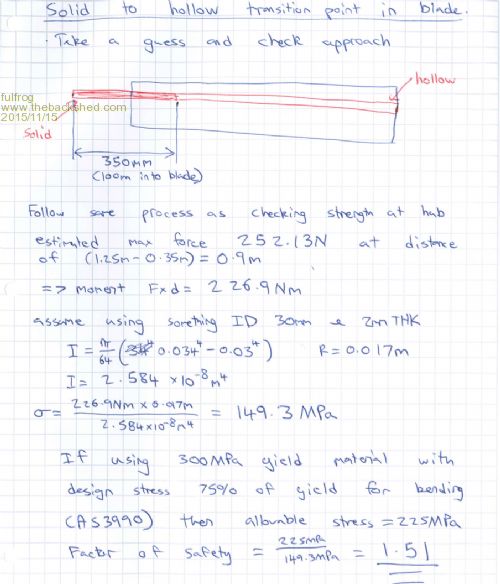
Thanks guys, it was this form that got me interested in windmills, i remember commandeering my dad into helping me make my first one when i was 12 or 13. none of them really fully functioned correctly, i have another biggish mill i've posted on here before. Link i decided to build a whole new prototype rather than trying to get all my mismatched parts to work, i wanted a design i could easily replicate something that is safe, efficient and easy to maintain. i also needed to show developments for my schoolwork designing a new turbine was the best option. I've put a video of the construction here Link it's not the most precise method of construction. but the blades are relatively the same weight, the blades all had the same amount of resin and glass and the shafts were all made the same. but it's a prototype, i think it would be best to use vacuum resin infusion, also replacing the shafts with a lightweight high performance alloy also making the ribs of that alloy. looking back on it now i think i may have gone a little overkill on the shafts. 32mm OD 2mm wall 1250mm and the first 350mm solid. i think its too heavy ( cant remember exactly but i think they weighed a bit more than 3kg each) only really realized it being an issue after constructing, but i only initially chose this through the calculations below. 
i'm waiting for my order of biaxial fiberglass cloth which i will use to further bind the leading edge of the blade. that stuff is hard to get in NZ. then i need to balance the blades somehow still thinking about the best possible method for that? i'm really interested to see how this is going to run once i put it up. Angus. |
||||
Downwind Guru Joined: 09/09/2009 Location: AustraliaPosts: 2333 |
You will need to give a good look at getting the blades in balance, as a few grams difference can make a huge change in the mill operation across the rpm range. With non perfect balanced blades you will get vibrations at different rpm ranges, this leads to early failure of the mill in unexpected ways. It is best to balance your blades around mid point, although many might not agree with this as it requires more weight compared to adding weight to the blade ends. You can more than likely just paint a coat of resin to each blade to adjust the balance as I have done in the past. Simply remove the stator and test how the blades balance out on the shaft. You should be able to stop each blade at any given point and it remains there, if not one blade is heavier than the others. Pete. Sometimes it just works |
||||
fillm Guru Joined: 10/02/2007 Location: AustraliaPosts: 730 |
Hi Angus, Well done and truly a credit to your abilities. There have been quite a few concerns raised here and I am sure you have a plan for the balance. If you are going to use your bearing housing for balancing I suggest you remove the seals while you are checking balance and just replace them and the grease later, its very easy to flick the seals out with a small screw driver. I would recommend that you put a manual furl rope into the mix as those blades at that diameter will be like a runaway as 1 x f&p gen or even 2 would not be able to keep things under control. I might be wrong as your cord looks a bit larger than the Alu GOE222 and it might slow things down a bit. All up , 10 out of 10 for the blades and the Vid, and will be interested to hear how it goes in a good NZ breeze.. PhillM ...Oz Wind Engineering..Wind Turbine Kits 500W - 5000W ~ F&P Dual Kits ~ GOE222Blades- Voltage Control Parts ------- Tower kits |
||||