|

|
Forum Index : Windmills : Breaking down a forklift battery bank.
| Page 1 of 2 |
|||||
| Author | Message | ||||
wallablack Senior Member Joined: 10/08/2011 Location: AustraliaPosts: 164 |
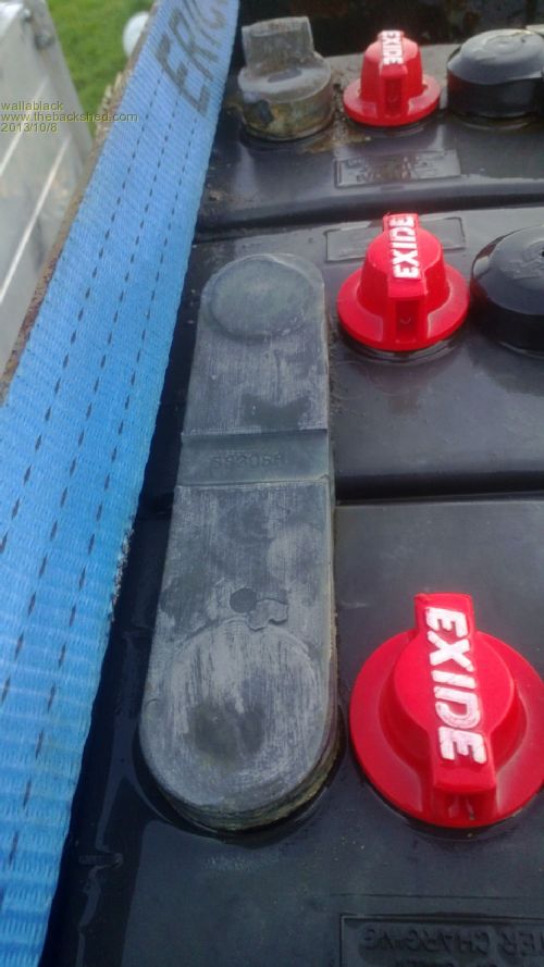
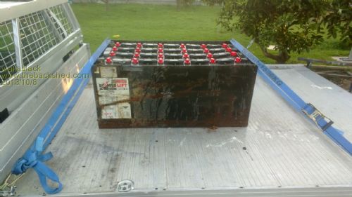
Hello all, I picked up a used forklift battery bank yesterday and want to break it down. It was out of a 1999 Nissan forklift and the batteries were replaced in 2011. The forklift was wrecked for the hydraulic rams and this was left over. The bloke that had them charged them every week or so and kept them in good nick so for $250 it was a worthwhile score. What I want to do it break all the batteries apart but I am unfamiliar with the links. Are these soldered on? As they are lead acid obviously a blow torch to soften the solder is out of the question. Can anyone offer some advice on how to remove these links? 

Foolproof systems do not take into account the ingenuity of fools. |
||||
| M Del Senior Member Joined: 09/04/2012 Location: AustraliaPosts: 155 |
I last had something to do with this sort of battery pack over 10 years ago. If the links are lead (and they look it) they are soldered on when assembled into the pack. I never connected them but we visited the supplier and from memory they used a machine with multiple heated irons to almost spot weld the connectors. We used to split them with a hacksaw for disposal/recycling if there were any decent cells left. Good cells ran a 24 volt trolley jump system. Once separated heat the links to bend them up to enable proper cable connection to be made. We drilled through and used 8mm bolt connections. It takes a very large tipped iron to heat them. Do not bend them too far as it was easy to snap the link. Mark |
||||
| Tinker Guru Joined: 07/11/2007 Location: AustraliaPosts: 1904 |
I would not consider trying to unsolder the links. Lead melts around 300 deg C, leaded solder at about 220 deg C. Too little difference and a big chance to melt the links if one can find a big enough soldering iron to attempt this idea. A hacksaw sounds much easier. Klaus |
||||
wallablack Senior Member Joined: 10/08/2011 Location: AustraliaPosts: 164 |
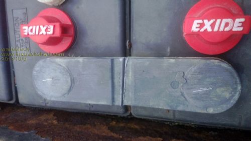
I ended up cutting the lead links with a 5" grinder with a wafer thin cutting disc. Being lead there was no sparks so safety was not really an issue. This way if I want to rejoin some together it is just a case of drilling a hole and tapping a thread then using a suitable bolt to re establish the connection with consideration to the current the bolt will have to carry....Personally I wouldn't try to melt the solder for risk of damage. Heating with a torch is out of the question due to the gases given off from the battery being flammable. The size of the lug left on the battery gives many options for connection. Even drilling directly into the post could be an option I will look at if there is enough to play with. 
Foolproof systems do not take into account the ingenuity of fools. |
||||
Downwind Guru Joined: 09/09/2009 Location: AustraliaPosts: 2333 |
Not much risk of gas explosion if the battery has not been on charge for a few day, hydrogen is only produced during charging and not while sitting around. I used a torch on my batteries and no big bang, it do pay to remove the caps and blow a little air into the top of the cells to remove any gas that might be sitting there, a bit of plastic tube and blowing with your mouth is good enough.(dont suck!) You dont want to heat too much near the posts as that can damage the seals and you will then get corrosion around the posts. After any heating use a wet rag to suck out as much heat as quick as you can. Pete. Sometimes it just works |
||||
| VK4AYQ Guru Joined: 02/12/2009 Location: AustraliaPosts: 2539 |
Hi All I have found the best way is to drill and tap the cut link and use stainless 6mm bolts to attach the connecting wires, just use a sleeve on the drill so you do not drill into the plastic battery top. All the best Bob Foolin Around |
||||
wallablack Senior Member Joined: 10/08/2011 Location: AustraliaPosts: 164 |
Thank you so much for the input, it is greatly appreciated. I am going to leave the full tab on them so I don't risk any damage. I am going to drill right through the cut so half a hole on one tab and half on the other. The bolt will then become the "connecting cable". I am having good results so far. I have broken it down to 4 12V banks and I charge the first one yesterday. 15V to free up up crap for a bit and then to 14V. I pulled the charger at 9pm last night and at 7am this morning they were sitting on 12.9V. Not a great voltage drop but I would believe with a longer deeper charge they will sit nicely. That is only 1 of the 4 banks though. Each battery is 413AH and a string of 6 gives 12V at 413AH. Correct me if I am wrong. If I build two strings of 12 batteries x 2v 413ah = 24V 413AH. Then connect the two positives and two negatives at the end of each string together we get a 24V 826AH battery bank. I have my finger and toes crossed that they all work out like the first 12V bank that I charge, just one damaged one will only give me one 24V 413AH bank. Or...could I connect them another way if a couple are faulty? Also am I correct in saying that charging time = AH / (divided by) charge current. So 413AH / 30A = 13.7 hours to charge. Foolproof systems do not take into account the ingenuity of fools. |
||||
| M Del Senior Member Joined: 09/04/2012 Location: AustraliaPosts: 155 |
Make sure you use a star washer with the serrated edge on the outside to ensure continuous connection. I have seen something like your proposal used before and the slightest movement of a cell can cause a loosening of the bolt and poor current flow. If I recall it was flat copper bus bar with no bend to allow for flex, it loosened the connector and part melted a post before separating. Good score, you should get a few years out of them. Mark Mark |
||||
wallablack Senior Member Joined: 10/08/2011 Location: AustraliaPosts: 164 |
M Del, I never even put that into considerations but a theory well worth considering. From this I think I will go to the idea of using a cable and lug connector using drilled and tapped holes to secure the lug. Foolproof systems do not take into account the ingenuity of fools. |
||||
Downwind Guru Joined: 09/09/2009 Location: AustraliaPosts: 2333 |
Lugs and cable sounds a lot of work, i would just beat some copper tube flat and bend a small horseshoe shape in the middle of it for expansion and alignment and drill 2 holes for the bolts. -^- Pete. Sometimes it just works |
||||
| VK4AYQ Guru Joined: 02/12/2009 Location: AustraliaPosts: 2539 |
Hi All I use strips cut from old copper HWS about 1 inch wide bent in a lop like the ohm symbol as Pete suggested very cheap if you have an old HWS All the best Bob Foolin Around |
||||
| Dubyagee Newbie Joined: 15/06/2007 Location: United StatesPosts: 21 |
I am the service manager at a Hyster forklift dealership. Heres how we do this. http://www.youtube.com/watch?v=vTTylGSuAgo#t=54 http://www.youtube.com/watch?v=aNMbmVCnA0k http://www.youtube.com/watch?v=J4sqUvRDAH8 http://www.youtube.com/watch?v=mnWqpcu8CvI Regards, Dubyagee |
||||
wallablack Senior Member Joined: 10/08/2011 Location: AustraliaPosts: 164 |
Great idea with the ohm shaped copper pipe. I am having trouble with my second 413AH 24V battery bank. I have had them up to 100% charge at 27.6V with 500W of solar and 750W of wind. When I leave them off charge over night and check them in the morning the charge controller reads 23.7V and 50%. This is with NOTHING connected to them. The charge controller is just a Chinese made Solar 80 but has been great in the past. If I remove the battery joiners they all measure 1.8 - 2.0 volts on my DMM. Am I looking at a buggered bank or are they just not getting a deep enough charge during the day? Foolproof systems do not take into account the ingenuity of fools. |
||||
| VK4AYQ Guru Joined: 02/12/2009 Location: AustraliaPosts: 2539 |
Hi Walla You will find that the regulator will not send the voltage high enough to equalize the cells on a 24 volt bank you will nee 32.5 for 15 mins then come back to 30 volts for 1 hour do this for ten cycles and recheck cell voltage if not above 2.2 after an hours rest you have a weak cell and if you are serious about preserving the bank fit a desulphator as well. I have brought back very degraded cells by this method so give it a try. When doing this put the low voltage cell on the top end of the string. Use your panel without a reg and use a piece of cardboard to cover some segments to regulate the volts manually while monitoring with a multi meeter All the best Bob Foolin Around |
||||
wallablack Senior Member Joined: 10/08/2011 Location: AustraliaPosts: 164 |
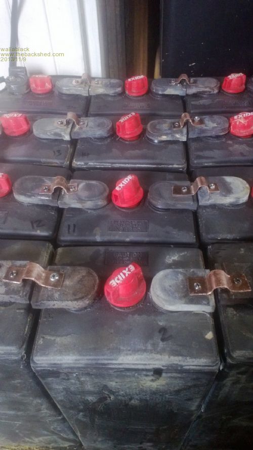
Well I finally got a chance to make some joiners to link the batteries together. I had a length of 1/2" copper pipe which I cut in half and flattened...works well. I picked up a PL20 from my boss for free...he just happened to have 4 of them in his shed from some trailer mounted, solar powered traffic lights that were on a truck that tipped over. They also come with 4 Trojan 6V T-105 225AH batteries each so I scored 16 of those to for a bit of free labour. I have run the batteries to 33V for 2 hours and they seem to now be holding charge really well. I got a desulfator but it seems to play games with the PL20 when it pulses so I put that on when the sun is gone at night...Did it do anything? Who knows. 
Foolproof systems do not take into account the ingenuity of fools. |
||||
fillm Guru Joined: 10/02/2007 Location: AustraliaPosts: 730 |
Desulfators are like dark matter in the universe , it is said to be there but is it, correct charging and looking after the batteries with a Hydrometer is the best option . You have scored "THE BEST" battery regulator that money can buy with the PL20 . I would be checking for heat in those tek screws you have held the Copper connectors on with when under load as there dose not appear to be much clamping surface area and force but if you are only pulling 20A its probably not a issue . PhillM ...Oz Wind Engineering..Wind Turbine Kits 500W - 5000W ~ F&P Dual Kits ~ GOE222Blades- Voltage Control Parts ------- Tower kits |
||||
wallablack Senior Member Joined: 10/08/2011 Location: AustraliaPosts: 164 |
Phill, I believe the PL20 is the best on the market now after owning one. You can practically do anything with these and battery maintenance with these is great. You actually got me on to the PL20 for dumping/resistive loading with the 2 rectifiers and external SSR which is the best method. The desulphator......myth or fact? I am hardly going to rip a battery open for the before and after shots but I cannot see a visual difference and whether it contributed to the rejuvenation of these batteries is anyone's guess but I was willing to give one a try for a $30 outlay. The size of the screws were an issue I had in mind too. I polished the tops of the terminals and also the copper for a clean contact and once I screwed them in I gave the copper a tap with a ball pein hammer to give even contact. Remembering that this is only an exercise to see if these batteries are worth keeping and using. From the original 24 I will select the best 12 for the bank, once this has been done connections will be more permanent and proper. Overall I am getting better results now that the PL20 is in use. The ability to Equalize for a while is what I think was the major contributing factor to the rejuvenation. Still wondering if I should align them for a 12V bank though. Foolproof systems do not take into account the ingenuity of fools. |
||||
| Warpspeed Guru Joined: 09/08/2007 Location: AustraliaPosts: 4406 |
The copper pipe saddles are an absolutely BRILLIANT idea !!! But I agree those nasty looking screws may cause you some grief over time. I would use fine threaded high tensile bolts with either very large thick washers, or multiple stacked thinner washers fitted on both sides. The idea is that a high tensile bolt can really be torqued down, stretching the shank of the bolt if the bolt is fairly long. Bolt stretch will keep both the nut and the joint tight. The secret here is bolt length. Very short bolts will not stay tight or clamp well, especially on something like lead which will slowly compress and creep over time. Long bolts with spacers or stacks of large diameter washers will do the clamping trick with ease, and be very long term reliable. A coating of thick grease will go a long way towards reducing corrosion on the bolts. I can see that you don't have a lot of room to play with with those short lead links. You might be able to reduce those links to half thickness by cutting away material from underneath, giving just enough room to slide in a washer and half height nut. Cheers, Tony. |
||||
fillm Guru Joined: 10/02/2007 Location: AustraliaPosts: 730 |
What "High tensile fine thread bolts into lead" , and how much torque. I would be saying min 1/2 UNC / UNF , 12mm whatever and Big Washers , but be careful when tightening . Might be OK into Brass but not Lead . The tapping with a ball peen hammer will just loosen the connections , and may-be use some Vaseline or similar under the straps, and look at draw filing the lead surface , again all dependent on Amp load. Keep away from old parallel banks it will be grief. PhillM ...Oz Wind Engineering..Wind Turbine Kits 500W - 5000W ~ F&P Dual Kits ~ GOE222Blades- Voltage Control Parts ------- Tower kits |
||||
| Warpspeed Guru Joined: 09/08/2007 Location: AustraliaPosts: 4406 |
You don't tap the hole! Use a high tensile steel bolt and a steel nut (and a washer) beneath the lead link. There is not going to be a lot of room underneath those lead links, but 6mm fine thread (1mm pitch) bolt should easily provide enough clamping force. A standard nut in that size is 4.8mm high, a half height nut 2.4mm high. Larger 8mm diameter bolts would obviously be better, but in this case there is probably not going to be enough room between the top of the battery case and those lead links. It may be possible to slip a thin file in there and open up that gap by filing away the underside of the lead links. From what I can see in the picture, there should be at least 4mm gap under there, and a half height nut and 1.6mm thick washer should just slide in. Cheers, Tony. |
||||
| Page 1 of 2 |
|||||