
|

|
Forum Index : Windmills : gearing VAWT & AC grid tie?
| Page 1 of 2 |
|||||
| Author | Message | ||||
| goldhunter_2 Regular Member Joined: 10/03/2010 Location: United StatesPosts: 57 |
First I'll say that a HAWT is not legal (I checked) to put high enough nor a large enough one to be more then decoration where I live, you gotta love city ordinances 
OK I spent the day looking for some smart drive motors at the junk yard but found none just regular electric motors though discouraged I still looked around at scrap i have to build a test VAAT with and this is what I came up with : 40ths aluminum sheet I can cut into 6" by 46" strips for the blades some 1/8" aluminum I can cut the top of the vawt out maybe 8"-10" diameter and attach the blades with aircraft rivets for the bottom I could cut another piece of alum but I am thinking of using a automotive flexplate (have several 12" and 13" diameter one to use then just rivet the bottom of the blades to the flexplate. I was thinking of the eggbeater style vawts just to be simple. and Iwant to use between 1 to 3 smartdrive providing I can find some. I estimate the height of this test vawt to be only about 40" tall and six to eight blade with the materials I have on hand so may only run one smart drive on this one. According to the weather service I looked up for my zip code 34953 we only have a average of 11.5 mph winds (I think There low) two towns up the road has 26mph average , But lets base the questions on there wind number of 11.5 mph average. Ok finial  I have three questions related to VAWT's I have three questions related to VAWT's
1) using a flexplate with a 12" diameter and a gear with matched teeth with a 1.25" diameter gives me a drive ratio of 9.6:1 (12" divided by 1.25" equals 9.6) this means for every time the vawt blades make one full rotation the gear driving the smart drive motor should make 9.6 turns thus speeding up the motor for better output. So will the 9.6 ratio get the smart drive motor turning over fast enough during a consistent but slow wind to produce productively? 2) wiring the smart drive allot of what I read people convert form the three phase AC to DC but I saw some grid tie inverters that take three phase ac wouldn't that just be easier and better for me to use? 3) Wiring question again, delta configuration is supposed to be less resistance higher current but lower voltage if I am understanding correctly. considering what i want to do is this the best wiring configuration for me to use? OK lets hear it but be gentle with me ...lol . |
||||
| electrondady1 Senior Member Joined: 12/02/2009 Location: CanadaPosts: 208 |
i build vawts i tried using a flex plate as a drive gear and the matching gear from a starter it makes and awful racket! i ended up building a dual rotor air core alternator by covering 2 14" flex plates with magnets. absolutely quiet! just judging by your description you will need more wind mill swept area in order to get the power you want. |
||||
| goldhunter_2 Regular Member Joined: 10/03/2010 Location: United StatesPosts: 57 |
well I originally looked at buying magnet but for enough magnets of decent size it gets expensive pretty quick , I was hoping to find one of the fisher style washing machine pancake magnets motors even went to a repair shop the other day to look for one but all they had are regular elec motor. I didn't think about the noise  but it will be out in the yard. maybe I could make a oil bath to quite it down. Where you running direct gear to gear or a chain gear drive system? but it will be out in the yard. maybe I could make a oil bath to quite it down. Where you running direct gear to gear or a chain gear drive system?
|
||||
| goldhunter_2 Regular Member Joined: 10/03/2010 Location: United StatesPosts: 57 |
update: I still haven't found a smartdrive motor:( but I have started to build a test VAWT and I machined a few parts yesterday for it . I ended up using a 13.63 diameter flexplate (was lighter then the other 12" one) and the same 1.25" diameter gear for the motor drive witch is now a final ratio of 10.9:1 it isn't a lot but better then a 1:1 ratio. I am using some type of old hub I found it has good bearings and a grease fitting which I liked having. I had to machine it a little but now the flex plate sits right on there , I notched the flexplete for the grease fitting, then machined a piece of aluminum tube to fit snugly over the hub , I cut some 1/8" aluminum plate in 11" diameter circles and the bottom plate I made a center hole the OD of the aluminum tube these will be welded later then the plate will bolt to the flexplate and hub assembly , I have a small plate to cap off the aluminum tube with a smaller hole in the center that fits a 3/4" aluminum pipe which is the main support for the VAWT blades an the top plate will be weld to this support. Trying to use materials I have as much as possible for the test means my VAWT is limited to about 40" tall and the blades and should be around 24"-30" diameter I know that's not ideal but I can always build another one later depending how this one preforms. Next I have to cut the aluminum sheet into strips for my blades , I'm still thinking on this as I was wanting 6"-8" wide blades but see most vawts with 2"-3" wide blades which may actual work better for attaching them to round plates but would be less surface area to grab the wind HUMMMM?????? I am cutting them form .40ths aircraft aluminum so those will need to be rivets to the round plates then I can work on a mounting bracket and keep looking for a motor. |
||||
| goldhunter_2 Regular Member Joined: 10/03/2010 Location: United StatesPosts: 57 |
ok here is a picture of it so far , it is just sitting together I still have more piece to cut out before welding an riveting it together 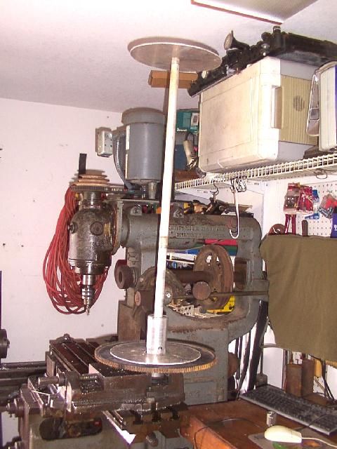 |
||||
| Warpspeed Guru Joined: 09/08/2007 Location: AustraliaPosts: 4406 |
A few random thoughts..... A 1.25 inch diameter gear will be very difficult to drive, and be mechanically inefficient when working as a speed increaser. If you need 9:1 then doing it in two stages of 3:1 and keeping all the diameters as large as possible will be far more mechanically efficient. Three phase alternators are always connected in star, delta connection can cause some big problems. Think about it. If the three ac voltages are not perfect sine waves all exactly alike and exactly 120 degrees apart, when you close the delta connection there will be a circulating current. This will load the alternator, heat up the windings and generally be very bad in all respects. Star connection allows some crappy looking waveforms to just add in series, and it will work fine. This is especially important with a rectifier load which distorts the ac waveform because only the peaks are loaded. Sure delta connection will work, many people do it that way, but it does not work well. If I was doing something like this this myself, I would probably couple up the F&P directly to the VAWT and just accept that the output voltage is going to be very low. At least it will be very mechanically efficient doing it that way. It then remains to find a way to increase the output voltage electrically (rather than mechanically) which will be much more efficient. The simplest would be to use three small step up transformers, that would be much less trouble than rewinding the F&P coils or building a gearbox. Each transformer primary would need to be connected between each phase and the centre of the star point which is normally not connected. You could try various transformers with different voltage step up ratios on just one phase to experiment with. When you have a good idea of expected typical wind speed, rpm, output frequency and voltage, then get two more similar transformers to finish the job. This sounds really Mickey Mouse, and in a way it is, but it also works surprisingly well !!! Try it and see. Ordinary 50Hz mains transformers that will invariably be much larger than the coils in the F&P wound with much thicker wire will work fine. If you end up getting say only a measly two volts from the F&P, and you wanted say 30 volts, you need a 15:1 ratio transformer. Much easier to arrange than a 15:1 step up gearbox, and more efficient. A 240 volt to 15 or 18 volt transformer would have about the right 15:1 ratio (for this example). *edit* Just realised you are located in the US, make that a 120 to 8 volt 60Hz transformer for this example. Cheers, Tony. |
||||
Downwind Guru Joined: 09/09/2009 Location: AustraliaPosts: 2333 |
Would a standard iron core transformer not saturate the core at high frequency from the F&P, might work fine up to 60+Hz but im not sure what will happen in the higher frequency range. Sometimes it just works |
||||
| goldhunter_2 Regular Member Joined: 10/03/2010 Location: United StatesPosts: 57 |
warp I can see some of what your saying , transformers maybe be a better way I was leaning towards gears as I was more comfortable working with them. I do agree that a gear train would be more effective I was just using what I had on had. The idea behind the gear was yes to speed up the motor but would also produce less resistance for the blade to spin. I have to admit I am a bit confused at your comment "mechanically inefficient when working as a speed increaser" could you elaborate some more? I have always thought that a larger Drive gear would increase the leverage thus making it easier to turn the smaller gear which provided the resistance form the magnets |
||||
| Warpspeed Guru Joined: 09/08/2007 Location: AustraliaPosts: 4406 |
Exactly the opposite in fact. At higher frequencies the flux swing in the core actually reduces, you need less turns to support a given voltage at higher frequencies. It is low frequencies that are usually the problem with transformers. For example, a winding rated at 20 volts and 50Hz will have the same flux swing at 2 volts and only 5Hz. The result of all this is that commonly available power transformers with mains voltage rated primary windings can operate over a very wide frequency range, provided the operating voltages are kept well down, which is not going to be a problem for what we wish to do here. Anyhow, it's pretty easy to try. Cheers, Tony. |
||||
| Warpspeed Guru Joined: 09/08/2007 Location: AustraliaPosts: 4406 |
Try and find a small high reduction gearbox, maybe from a clock or small geared motor. These usually have extremely small pinions, the teeth are often cut straight into the small diameter shafts. Now try to turn the gearbox in the reverse direction by hand so it acts as a speed increaser with zero load on the high speed output shaft. You may find it IMPOSSIBLE to physically turn by hand due to the high friction and low mechanical efficiency. Worm gears are even worse, they simply don't work transmitting power in the reverse direction. Building an efficient gearbox to reduce speed is dead easy. Building an efficient gearbox to increase speed will be much more of a challenge, and the higher the ratio the worse it gets. Commercial gearboxes built to increase speed almost invariably use epicyclic gears, which is way beyond most of us for a hobby project. Cheers, Tony. |
||||
Doug Regular Member Joined: 11/05/2010 Location: New ZealandPosts: 41 |
Goldhunter_2 There is an alternative to the smart drive that may be easier to find in your area. It comes out of the gentle annie washing machine. It only produces about 5 amps but good volts low in the rpm range. The only draw back is pretty fierce cogging on start up. Once going though its not really a problem. See link for details. http://www.thebackshed.com/forum/forum_posts.asp?TID=3113 May The Power Be With You |
||||
| goldhunter_2 Regular Member Joined: 10/03/2010 Location: United StatesPosts: 57 |
warpspeed, Hummmm I am going to have to think on this for a bit  May even have to cut some new gears for a drive train like you said earlier but right now I don't have any steel to cut them out of. i think I'll see if I have a clock that isn't digital and try what you said maybe it will help me decide thanks May even have to cut some new gears for a drive train like you said earlier but right now I don't have any steel to cut them out of. i think I'll see if I have a clock that isn't digital and try what you said maybe it will help me decide thanks
|
||||
| goldhunter_2 Regular Member Joined: 10/03/2010 Location: United StatesPosts: 57 |
Doug , I think I may have seen a motor like that the other day at one of the junk yards I visited but I'm not sure it would work with the clogging issue , my thoughts on gearing the VAWT where to help add torque to prevent low speed clogging on the smart drive which isn't supposed to be bad anyway but I am try to make it function in as low of wind speed as possible |
||||
| Warpspeed Guru Joined: 09/08/2007 Location: AustraliaPosts: 4406 |
The trick to low frictional loss is to keep all the diameters as large as possible, and sprockets will be a lot more practical to work with than spur gears. A nice loose chain that dips into an oil bath, and some ball bearings should be fairly easy to make, will run silent, and be very reliable. Junked bicycle parts come to mind... Trying to turn a very small diameter pinion with a very large diameter drive gear is the worst possible way to go about it. Gears can be made to work efficiently, but again, only if the diameters are kept inconveniently large. Cheers, Tony. |
||||
| goldhunter_2 Regular Member Joined: 10/03/2010 Location: United StatesPosts: 57 |
gears are laying side ways for this one so it be just as easy to make a oil pan for the whole thing but I got other issue to consider now first...lol I actual considered a bike spokets with chains so I could change the gears when expecting a big storm but was originally hoping to stay away for the belts and chains You know I have been all though my attic this afternoon looking for a old clock 
. |
||||
| Warpspeed Guru Joined: 09/08/2007 Location: AustraliaPosts: 4406 |
Another completely different way to go about all this would be to build a very large diameter axial flux generator completely from scratch. Use a single wave winding and it could directly produce a high output voltage at extremely low rpm, as well as having zero cogging. No gearing required !! Cheers, Tony. |
||||
| govertical Guru Joined: 11/12/2008 Location: United StatesPosts: 383 |
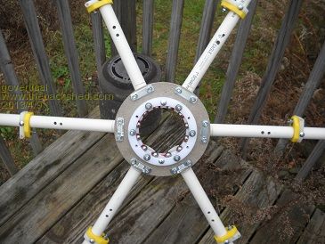
Power in the wind Hi, I am working on a similar project. Just some photos of my gear drive. The link will tell you about how much power you can generate for a set size blades and at what windspeed. A 4x8 foot VAWT should produce about 5 amps at 10 MPH using a 12 volt battery as a test load.. You may need a power conversion circuit to prevent turbine stall. I have been testing with a modified F&P. I plan to operate more than one VAWT in parallel. I am working on the control circuitry now. I am still testing, good luck with your project and I hope to see some more photos. just because your a GURU or forum administer does not mean your always correct :) |
||||
| goldhunter_2 Regular Member Joined: 10/03/2010 Location: United StatesPosts: 57 |
govertical, you have put allot of time into yours just form looking at the pictures nice work. and that link is awesome  Mine is smaller its just meant to be a test to see what type of performance I can expect over a several month period before building something bigger but that link you provide will be a handy thing for estimating . Mine is smaller its just meant to be a test to see what type of performance I can expect over a several month period before building something bigger but that link you provide will be a handy thing for estimating .
What thickness material are you using to cut those polymer gears out off and aren't you concerned with melting/heating up the teeth in a higher wind situation? I see your using larger gears like warp mentioned earlier what did you end up with for a final drive ratio on yours? |
||||
Downwind Guru Joined: 09/09/2009 Location: AustraliaPosts: 2333 |
I would think 60 watts in about 5m/s (10mph) a rather poor output, like not ever worth the build cost. Using gearing of any type in a small mill will always result in a high efficiency loss, with the losses often equal or greater than the returns. A 1:1 ratio is the only way to extract efficient energy from the wind in smaller mills. (it might seem a big mill to the builder but its still a small mill in size) Gearing in small mills is nothing more than a bandaide over a bad mill design and poor alternator match for the mill design/construction. There is 2 ways to build a mill, from alternator up, or alternator to suit the blades. Either way the alternator needs to somewhere match the blades for torque and rpm. You are far better to step back and consider a alternator redesign than charge ahead with great ideas of gearing ratios that will only return huge energy losses. For a low speed mill you need lots of turns on the coils to generate a higher voltage for low rpm. IMO you are wasting your time using gearing, build the stator to suit. Pete. Sometimes it just works |
||||
| govertical Guru Joined: 11/12/2008 Location: United StatesPosts: 383 |
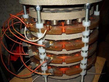
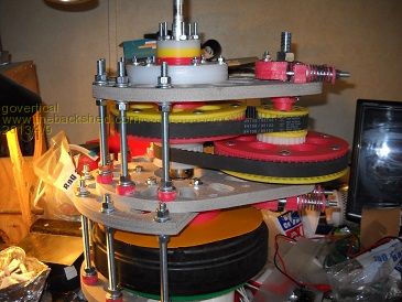
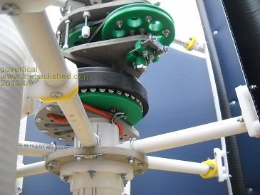
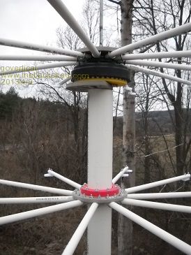
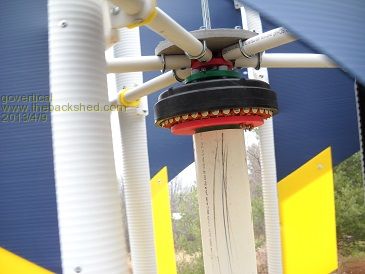
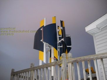
Hi, does 10 amps at 12 MPH sound better? It depends on your average wind speed. I have been doing a lot of experimention over the past few years. Because I am using a modified F&P I am using a drag style blade; J shape; It is easy to fabricate and low cost. It took a while to find the design that would work with the F&P that I could fabricate. A air core axial flux PMA would work better with lift style blades, but the F&P is low cost and saves a lot of fabrication man hours. Lift or drag blades the amount of power that can be generated is still determined blade size and wind speed. Lost power at the stator adds a lot confusion. Adding a power conversion circuit or MPPT makes a big differance. MPPT Video The names and hardware used is not important, the info at 1 min 20 sec is:) I have tested V belts, timing belts, and gears drives. Gears are the easiest for me to fabricate that are low cost and over heating is not a problem. I make the gears from plastic kitchen cutting boards, again low cost. 1 to 3 is a good ratio. Starts spinning at 3 MPH. I am not able to fabricate a large diameter PMA. Using a large diameter mast bearing allows for larger blades to be used and really helps provide stability. I live in a low wind area, which is why I am planning to operate more than one VAWT in parallel. There is a lot of misleading info about VAWTs. But the technology and information is changing. I did not intend to take over the thread and I hope my suggestions help. 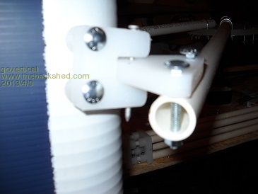
CalTech VAWT farm VIDEO just because your a GURU or forum administer does not mean your always correct :) |
||||
| Page 1 of 2 |
|||||