
|

|
Forum Index : Windmills : VAWT, F&P, analog MPPT project
| Page 1 of 6 |
|||||
| Author | Message | ||||
| govertical Guru Joined: 11/12/2008 Location: United StatesPosts: 383 |
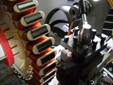
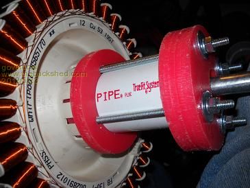
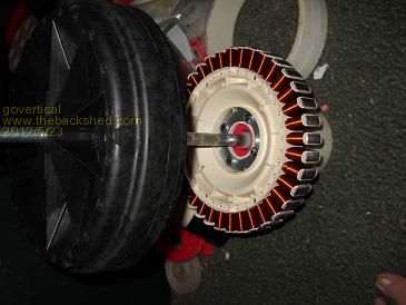
Greetings, I started a F&P PMA project. The stator and rotor are mounted using a similar design that other projects are using. I plan on using the PMA with VAWT blades and a analog MPPT circuit (Buck converter with manual adjusted duty cycle) to charge a 12 volt battery. The stator and rotor were a bit off center so I turned down the stator a small amount and now the rotor spins freely without touching the stator, still has small amount cogging. I heard the plastic of the F&P brakes down when exposed to sun light. Search for solutions. What weatherization is needed for the F&P? Comments welcome 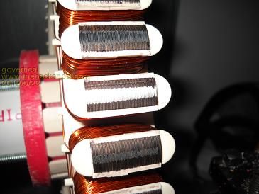
just because your a GURU or forum administer does not mean your always correct :) |
||||
| Gizmo Admin Group Joined: 05/06/2004 Location: AustraliaPosts: 5078 |
I've had a few F&P stators exposed to the sun and some are OK, some get a bit dusty as the UV breakes down the top layer of the plastic. Easy solution is to just paint them in a UV resistant paint. This also protects the stator lamination from rust. Nice work on the bearing housings. HDPE? Glenn The best time to plant a tree was twenty years ago, the second best time is right now. JAQ |
||||
| govertical Guru Joined: 11/12/2008 Location: United StatesPosts: 383 |
Hi, kitchen cutting boards. I think it HDPE. Basically I am using the same design that I used on other projects. I always avoided the F&P because the output was so high. I did not know how to control the output. I learned a lot when I did the buck converter project. I am increasing the input voltage limit of the circuit to 450 volts DC. The new parts for the circuit just arrived and it will me a few days to build the new circuit then I can test the F&P using a drill press. I will post results when a available. Thanks for info. just because your a GURU or forum administer does not mean your always correct :) |
||||
| govertical Guru Joined: 11/12/2008 Location: United StatesPosts: 383 |
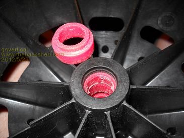
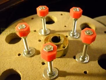
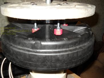
Hi, I needed away to secure the mag rotor to rotating center shaft. I did not want to weaken the mag rotor by drilling holes in it. My solution was to add coggs to the Blade rotor plate and the coggs will push the mag rotor. 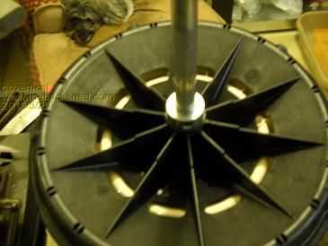
just because your a GURU or forum administer does not mean your always correct :) |
||||
| govertical Guru Joined: 11/12/2008 Location: United StatesPosts: 383 |
Hi, F&P open voltage measurements. 12 coils per phase, 3 phase star, phase to phase resistance 37 ohms, load 450 volt 470uF capacitor. RPM________Voc DC 100_________130 150_________180 200_________230 250_________280 300_________330 just ballpark measurements, when circuit is operating the input volts equals half of the open circuit voltage. just because your a GURU or forum administer does not mean your always correct :) |
||||
| govertical Guru Joined: 11/12/2008 Location: United StatesPosts: 383 |
Improved mag rotor coggs 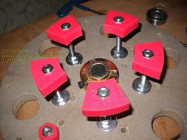
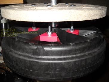
just because your a GURU or forum administer does not mean your always correct :) |
||||
| Jarbar Senior Member Joined: 03/02/2008 Location: AustraliaPosts: 224 |
Hi govertical,with your manufacturing skills try making the tool described here http://www.thebackshed.com/windmill/articles/decoggingFP.asp they twist easily and cogging disappears.Good luck. 
Anthony "Creativity is detirmined by the way you hold your tounge".My Father "Your generation will have to correct the problems made by mine".My Grandfather. |
||||
| govertical Guru Joined: 11/12/2008 Location: United StatesPosts: 383 |
Hi, results from today’s stock F&P and Buck converter tests: I replace the failed diode with five 3 amp 400 volts diodes and connected them in parallel. After increasing the PMA RPM above 100 the timing signal became unstable and the mosfet and diode array became very hot. Highest temp reading was about 140 degrees Fahrenheit. Then the mosfet or diode array stopped working. I will have to investigate to determine which one or both failed. Before the failure I was able to observe at shorter duty cycles the buck converter stopped converting and was feeding large voltage values into the battery, sometime above 100 volts. Conclusions from today’s test: 1. The stock wiring of the F&P produces a voltage much to high to be used with a buck converter to convert down to 12 volts for battery charging. The stator should be re-wired so that multiple phase coils are connected in parallel to reduce max voltage output to 50 volts for the max RPM of a turbine. Because of the quality of the materials; the plastic holding the stator together and the time involved to re-wire the stators I believe it is much easier for me to fabricate the PMA using established fabrication techniques. 2. After reviewing component cost and availability I am pursuing 5 amp power module configuration with single timing controller board, so for a 15 amp output would require one controller board and three power modules. I am not sure if it will work. What I need to find out is as more power modules are connected in parallel can the switching frequency remain constant, or does the switching frequency have to increase because each power module will have its own inductor and connecting the modules in parallel will reduce the inductance and cause the inductors to saturate. I am not sure and comments are welcome. just because your a GURU or forum administer does not mean your always correct :) |
||||
| Warpspeed Guru Joined: 09/08/2007 Location: AustraliaPosts: 4406 |
If you plan to operate at those relatively high rpm, then rewiring your F&P for a lower voltage and a higher output current would definitely improve overall efficiency. Cheers, Tony. |
||||
| govertical Guru Joined: 11/12/2008 Location: United StatesPosts: 383 |
Hi, the last test with the stock F&P I used a 20 amp 400 volt 280 watt IRFP460 N channel mosfet. I made a mistake and I did not increase the inductor value. I recalculated and fabricated a 3.0 mH air core inductor. It weight is 3 lbs with a 2 inch ID center. I used 13 AWG 260 turns. I do not know how well it work, but I will test the stock F&P one more time. The biggest problem at this time is finding a way to limit the input voltage. I am searching for a solution. 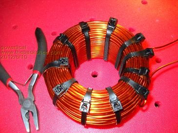
just because your a GURU or forum administer does not mean your always correct :) |
||||
| Warpspeed Guru Joined: 09/08/2007 Location: AustraliaPosts: 4406 |
Do you have a large electrolytic capacitor after the three phase rectifier ? Without that, there will be some very destructive voltage spikes once the buck regulator starts switching. That choke looks very good. Should start getting pretty hot around ten amps. 3mH is a good choice for around 300v (or less) at 20 Khz. Cheers, Tony. |
||||
| Gizmo Admin Group Joined: 05/06/2004 Location: AustraliaPosts: 5078 |
In case anyone's missed it there is a page about rewiring the F&P for lower voltage. http://www.thebackshed.com/Windmill/FPRewire.asp Its a fairly easy process. Glenn The best time to plant a tree was twenty years ago, the second best time is right now. JAQ |
||||
| govertical Guru Joined: 11/12/2008 Location: United StatesPosts: 383 |
Hi, I several 450 volt, 470 uF caps. Again I not sure how they work. I am having trouble finding large voltage caps. Suggestions for a good value input capacitor are welcome. 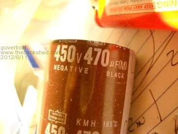
just because your a GURU or forum administer does not mean your always correct :) |
||||
| Warpspeed Guru Joined: 09/08/2007 Location: AustraliaPosts: 4406 |
The bigger the better. Look at the dc voltage across the capacitor with your oscilloscope. If there is a lot of high frequency ripple at the Buck Regulator switching frequency across that capacitor, more Microfarads will definitely help. Just remember, if there is ten amps going into your battery, when the MOSFET turns on, it is going to try to pull ten amps from your F&P, even if it is at up near +300 volts. Obviously that cannot happen, but ten amps still has to be sourced from the Buck Regulator input capacitor for the very short period when the MOSFET is conducting. That big electrolytic is a very important part of the Buck Regulator. It will be constantly being charged by the F&P at low current, but have to repetitively source some very high current peaks during the MOSFET conduction period. Cheers, Tony. |
||||
| govertical Guru Joined: 11/12/2008 Location: United StatesPosts: 383 |
Hi, is it possible to use high voltage capacitors in series to divide the input voltage to a more useable level? just because your a GURU or forum administer does not mean your always correct :) |
||||
| Gizmo Admin Group Joined: 05/06/2004 Location: AustraliaPosts: 5078 |
No, not with DC. Caps only pass alternating current, not DC current. Plus this type of circuit is a voltage divider, OK for taking measurements or tiny loads, but no good for any real current, very in-efficient. Glenn The best time to plant a tree was twenty years ago, the second best time is right now. JAQ |
||||
| govertical Guru Joined: 11/12/2008 Location: United StatesPosts: 383 |
Hi, I completed new concept drawing for the buck converter. Basically it is the same circuit as before. Each parallel buck converter will use a IRF840 n channel and it own bridge rectifiers. Again I am sure if it will work and comments are welcome. 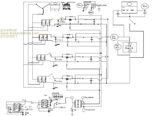
just because your a GURU or forum administer does not mean your always correct :) |
||||
| Warpspeed Guru Joined: 09/08/2007 Location: AustraliaPosts: 4406 |
That should work. I would reconsider placing the on/off switch in the negative side of the Vcc voltage regulator, put it on the +ve input side. Another thing to think about. If one power MOSFET shorts out, it will likely take out all the rest, because the gates are all joined directly together. It would isolate any damage if each MOSFET had it's own isolated gate driver. While that won't make it work any better, it will limit damage to one dead MOSFET, and probably it's own gate driver instead of very likely causing a total catastrophic failure. With these types of power electronics, it is all too easy for one component to die, and take out just about everything else. Apart from the cost and work of replacing many parts, it can be just about impossible to identify the original cause of the problem if the whole board is a blackened and burned mess. If one component dies, it is usually fairly easy to figure out why and do something about it so it does not happen again. Total devastation without knowing what happened can be very demoralising, particularly if it happens more than once. Cheers, Tony. |
||||
| govertical Guru Joined: 11/12/2008 Location: United StatesPosts: 383 |
Thank you for the great suggestions. It does make sense to go with a slam dunk. Thanks again. Some photos of the power module circuit lay out. 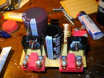
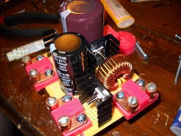
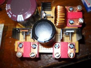
just because your a GURU or forum administer does not mean your always correct :) |
||||
| govertical Guru Joined: 11/12/2008 Location: United StatesPosts: 383 |
Hi, making progress. I only have enough parts to fabricate three Buck power modules. It is enough to test with. I still have to route wire connections and fabricate controller board. 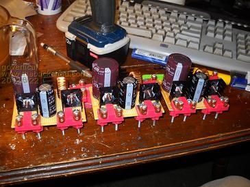
just because your a GURU or forum administer does not mean your always correct :) |
||||
| Page 1 of 6 |
|||||