
|

|
Forum Index : Windmills : The Mann Duel Smart Drive
| Page 1 of 2 |
|||||
| Author | Message | ||||
| BobMann Senior Member Joined: 30/06/2011 Location: United StatesPosts: 134 |
I started to build a Duel Stator using the 60 F&P stator and my Neo Magnet Drum set up. I had all ways planned to add a second stator in side when I started the design. I am trying to keep the coging down which with my the first design I was at 14 inch pounds at brake away. So here is some of pic of the build. I am trying some thing that I belive have not been tryed before. I use 2 rows of Neo Magenet set in a offset lay out to help lower the cogging. I am trying to stack 10 pound of sh*t into a 1 pound bag. I had to cut the stator that sticks in to the drum all the way. By cuting off and thing the is passed the coils. I tryed a few ways to hold each stator by them self to the axle shaft.A had a few not cut it. I still need to clock the stators to see if I could drop the cogging numbers and if it would help on power out put on the test runs. I had to do more cutting here. I got what I was looking for. I needed to mount the inner stator in a way so I could find the sweet spot. By rotating it from the outside end. I made up the sleve to hold it together Here is how I held it all together and still can spin it say 20% +- if needed. I added the allens as to hold it together and as a set of locating pins too. I wired it up like Bob from Down Under had showed me. I used a pair of colars to holt it to the axle shaft I still had to play with the depth in to the drum so not to grind up the inner coils. It looks like I should hit the 3000 Watt marker at a low RPM with this one. I am ready to do power test and cogging tests the cogging is about the sames as the ones with one stator. I need some help on the best wiring of the stators they are all hooked up to bar strips one for each stator to make it easy to do jumping from one to the other. Delta or star. This is not my strong point. The other is you can see were I am going with the cogging part. Has any one worked down this path there is a few more compantion that can be tryed. This is a hard build a lot of Neo Magnets pulling every were. I am hoping to have them all trained not fight me. For my needs I will use the stators wired the way there are no cutting or grouping coils please at this time of the build we can do that later. One more thing I am getting a lot of emails on the Mann Smart Drive using a HAWT blade set up. I do not have one at this time to sell I kind of missed this market. I have spent so much time on my VAWT. If some one has a low cost solition please run it by me. Thank you all Bob Mann |
||||
| Gizmo Admin Group Joined: 05/06/2004 Location: AustraliaPosts: 5078 |
One thing I've learned over the years, EVERYTHING has been done before 
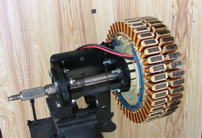
My own attempt many years ago. It worked, but it had problems because I was using two of the plastic magnet hubs fibreglassed together, and there wasn't enough strength in the plastic, so it scrapped the stator. But you're using a steel magnet hub, so you will have better luck. I'm pretty keen to see how this goes Bob, keep us posted. Glenn The best time to plant a tree was twenty years ago, the second best time is right now. JAQ |
||||
| BobMann Senior Member Joined: 30/06/2011 Location: United StatesPosts: 134 |
I was hoping you would take a look at it. I had seen your dual unit before. the point I am trying to make is with the Neo Magnets and steel drum by stagering and and slanting with adjustment of the stator. Can we over come the cogging to cancel out some of it out of the start up brake away. and can we adjust the sweet spot for power output. See you will never kill the drum or bearings in this setup so it can be a very simple build from that point. As you show in your pic.There is a lot of iron there to cut, weld, machine to boot. Bob Mann |
||||
| Gizmo Admin Group Joined: 05/06/2004 Location: AustraliaPosts: 5078 |
Yes I think you could overcome the cogging. The stators need to offset by a degree or two, you would need to experiment to get the sweet spot. If you assemble it so the stators are slightly loose, so they find their own point of max attraction, or worst cog, then take off the magnet hub and rotate one stator by one degree or so before tighting it up. You have a lot of testing ahead of you, but I'm confident it can be made to work. If your sticking to low RPM, then dont worry about rewiring the stator just yet. You will need a separate bridge rectifier for each stator, as they would be slightly out of phase with eachother. Glenn The best time to plant a tree was twenty years ago, the second best time is right now. JAQ |
||||
| brucedownunder2 Guru Joined: 14/09/2005 Location: AustraliaPosts: 1548 |
Hi Bob ,, I had a go at dual F@P some years back, must be 10 by now... I found that the fibreglas or plastic rotor casings were just too flexy--yours are steel so should be good.. I machined a wide wedding ring from stainless steel pipe to seperate the stators, that part worked well,,as I could adjust the inner and outer stator in the same plane a few degrees.. .. I also made a couple Neo magnet conversions that were around the 600 watt ,even more.. output. I follow every post here every day ,,wish you well .. Bruce. 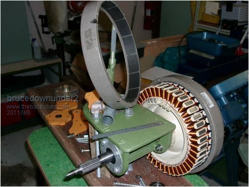
here you can see the second rotor ring containing the ceramic magnets machined and ready for fibreglassing to it's mate.. Bushboy |
||||
| Gizmo Admin Group Joined: 05/06/2004 Location: AustraliaPosts: 5078 |
Hey Bruce those lasercut steel parts bring back memories 
Glenn The best time to plant a tree was twenty years ago, the second best time is right now. JAQ |
||||
| VK4AYQ Guru Joined: 02/12/2009 Location: AustraliaPosts: 2539 |
Hi Bob Very nice addition to the F&P evolution, as you can see from what our guys have done, it has all been tried before but your brake drum and neo magnets make it a real possibility for advancement, the biggest problem is the six wire output and associated slip rings that could be an issue if used on a HAWT. I look forward to your test results and output configuration. Keep up the good work. All the best Bob Foolin Around |
||||
| BobMann Senior Member Joined: 30/06/2011 Location: United StatesPosts: 134 |
Hello Bob kind of late for you I am just getting started. For the VAWT no problem. As I said I am going to step up to the HAWT. I am looking for a low cost solustion for the blades and tail and motor holder. You will need a separate bridge rectifier for each stator, as they would be slightly out of phase with each other. I can set it up to do the recifiering top side and bring it down DC with 2 wires. Most people with not have run a lot of wire. I real will hate to add a slip ring set up.So I am going to test a welding cable group down the pipe say 6 feet of it they have been using it in the USA for years. as it twists up a bit it alls go,s back to a hanging postion after the wind die down. 
here is one blade and tail set up I will test. Jeff was to sell my VAWT one year later and over 13000 views on this site not a one sold HUM and no leads. But I sell them off EBAY with just a few hundred view??? I am game for any one that wishs to work with me on a low cost set up for my USA market. I wish not to step on any one,s toe, Down Under. Bob |
||||
| VK4AYQ Guru Joined: 02/12/2009 Location: AustraliaPosts: 2539 |
Hi Bob I have one of these 10 blade turbines and found it quite useful on winds over 5 MS, and really comes on above 8 MS unfortunately the wind is not that good at my place most times but I could see them being very good on your water tower. I am thinking of making a bigger diameter hub to get some more torque from the blades at low speed. The people that market them concentrate on their auto alternator conversion that needs a lot of rpm to get the power output. Your lower speed unit may over load the blades at lower speeds, but well worth a try. I have tried them to 2000 rpm mounted on a trailer so they can certainly hold together, I do think a bigger version would be a real winner but haven't seen anybody making one yet (80 to 90 inch diameter) I use a no slip ring set op on one of my mills for 2 years now, it uses a piece of marine quality bungee cord on the tail which allows two turns in either direction then it pulls it back, before the bungee cord I broke the wires several times from winding up to much. 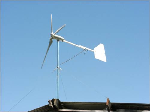
Not at all hi tech but it works good. with this set up you could use a six wire down feed and allow all sorts of voltage / current options suited to the clients needs. I do not think you will have any problems stepping on toes here in Australia as most guys are in the hobby side of things and the commercial dealers are concentrating on Chinese mills, these are very hard to compete with price wise even if Finnish quality is a bit suspect. All the best with your enterprise. Bob Foolin Around |
||||
| BobMann Senior Member Joined: 30/06/2011 Location: United StatesPosts: 134 |
Thank you Bob I like the cord. I have my friend Stev that designs VAWT wing making up a CAD for a 6 ft and 4 ft blade each it will be a 3 blade design to bolt to the hub. We will use 12 inch PCV pipe with the water jet to cut them out just for testing too. The cost of the PCV is $16 a ft we may get 3 blades out of one 6 ft pipe. I am going to try a Ginlong Technologies Co.,LTD. inverter grid tie 2 killer watt one for testing has any one used them. It looks like it has a good range to match my turbine. Bob Mann |
||||
| VK4AYQ Guru Joined: 02/12/2009 Location: AustraliaPosts: 2539 |
Hi Bob I have tried the PVC pipe blades but was not impressed with them, the best blades I have tried are the one that Philm has on the forum they are so much ahead of the rest for efficiency. They are not the cheapest but are by far more versatile, as they come in 3 meter lengths so you can cut and try all sorts of combinations. I find that they are up and running before other types even get moving, not always making electricity but they are moving ready to catch a breeze as it comes along. http://www.thebackshed.com/windmill/Trade/AlBladeOrders.asp For low to medium speed blades they perform better than all else I have tried, but they do tend to loose efficiency at high speed and are inclined not to rev out, so to me this is a positive as they are easier to control, i am picking up a set to make a 24 foot blade set for a 5 KVA axial turbine I am playing with, with getting 1.5 KW in slow wind speeds up to 10 KW at 20 MS. It will be a high voltage unit with transformer matching for different voltages. I believe the Ginlong Inverter with MPPT works very well but I haven't tried then myself due to financial constraints, when i can afford one I will go for the 5 KVA one for my machine, slowly slowly so as not to break the bank. All the best Bob Foolin Around |
||||
| BobMann Senior Member Joined: 30/06/2011 Location: United StatesPosts: 134 |
I had looked at his blades to like them a lot it was a shipping cost that killed it for me. I may still try rhem latter. Bob Mann |
||||
| KarlJ Guru Joined: 19/05/2008 Location: AustraliaPosts: 1178 |
Bob I have the dual stator PhillM machine on the farm. good for 700W. I can tell you 3000W from an F&P would need magnets the size of beer cans.... Iron cores make F&P law of diminishing returns. Double the magnets, get 100% more. quadrouple the magnets only get 120% more. keep it simple, far more satisfying that way, oh and forget the toy blades, if you have a decent blade set, cogging pretty much not relevant any more. My dual starts before the anemometer does! did i mention that it did 6kWhrs the other day -to the grid after all the lines losses, battery losses, inverter losses.... not bad for a couple of old washing machine motors 
I run Phillms blades and as long as you are intelligent there is no problem with them. my 3.2m set have seen pretty close to 1000rpm and thats hiking for a 3m blade set! STEEL inserts and a proper hub and balance are mandatory  Luck favours the well prepared |
||||
| BobMann Senior Member Joined: 30/06/2011 Location: United StatesPosts: 134 |
Hello We need to look out side of the box here. my output with my Mann Smart Drive is docmented with the one stator. 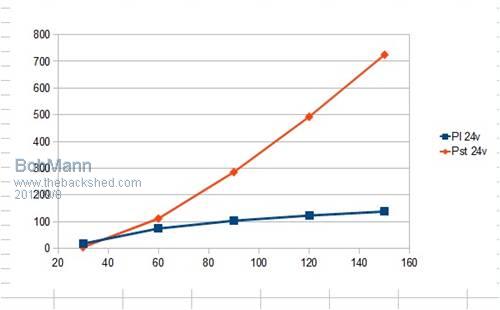
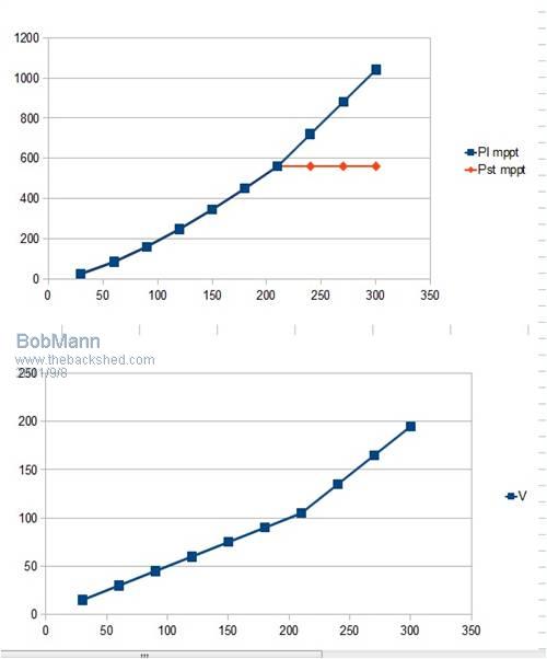
These numbers are for a 300 RPM used on a VAWT. And if you look at Bobs from Down Under he is showing very close numbers on his build. Hi Bob, 3 x 1m + Pack & handling = $170AUD Express Post = $125AUD Total = $295AUD I still need to Make up the hub and tubes with supports I will bite the bullet soon I would love to show them working in the USA on my water tower test site. Bob Mann |
||||
| Perry Senior Member Joined: 19/11/2009 Location: Posts: 190 |
Bob, Your output is not documented by that graph. That's a theoretical curve by someone that hasn't even tested it. Will you ever post actual numbers taken from your turbine? You ran it throughout a tropical storm. Can you post some of that data? Don't want another sales pitch, just an output graph. Perry |
||||
| BobMann Senior Member Joined: 30/06/2011 Location: United StatesPosts: 134 |
I stand by my graphs Perry wrote: ------------------------------------------------------------ -------------------- I wouldn't normally hound someone for data but you keep plugging this and posting on multiple threads at multiple forums that people should buy your system. So is it out of line to ask for some performance data? What charts have you provided? I guess I missed them. All I have seen is Steve's predictions and models based on no testing. Maybe I am wrong? ------------------------------------------------------------ -------------------- Perry, you have so little faith in my modeling ability. :-) Just to get all the info out there, this is how I figure out the power (voltage, or current) from Bob's Smart Drive. 1) OCV = RPM * 1.0 (If I ever get more careful measurements, that 1.0 might be adjusted a little, but I think it's very close.) 2) Take a guess at R (resistance) of the alt, say 10 ohms or so. 3) Current (I) = (OCV - Vload) / R 4) Calculate R based on the current: R = 7.5 * (1 + .1 * I + .03/5*I^2 + .03/5 * I^3) The R you calculate and your initial guess will be different. Go back to Step 2 and Guess at an R somewhere between your initial guess and the results of #4. When your guess and the #4 results are close (0.1 ohms or so), you are done. This is the method I used to generate my graphs. Bob recently gave me two current measurements. The real results and the results of my model are as follows: 81 RPM Measured short ciruit current: 4.69A Predicted: 4.76A Error: 1.4% 103 RPM Measured short circuit current: 5.10A Predicted 5.29A Error: 3.7% For a model that I came up with in 45 minutes or I'd say that's a pretty good fit! __________________ Steve Thank you Steve for doing the math that is some thing i could never do right. Bob mann |
||||
| Perry Senior Member Joined: 19/11/2009 Location: Posts: 190 |
Bob, Thanks for the clarification and posting the details of Steve's theoretical model. Would you be willing to post any of the performance data from the turbine as it was whirling away up on the high tower in the tropical storm? Perry |
||||
| Rastus Guru Joined: 29/10/2010 Location: AustraliaPosts: 301 |
Hi VK4AYQ Bob, Please ellaborate on your comment "thinking of larger hub to increase torque at low speeds" for 10 blade hub.Cheers Rastus see Rastus graduate advise generously |
||||
| VK4AYQ Guru Joined: 02/12/2009 Location: AustraliaPosts: 2539 |
Hi Rastus I was referring to the blade hub on the high speed blade set, the diameter is only 1.5 meters as standard and I have found that they will make plenty of RPM on light loading but lack the torque to run heavier loads, by increasing the effective hub diameter it gives more swept area and therefore more power lower down in the rpm range and should slow the top end RPM slightly. As they are inclined to go very fast above 15 MS this could overspeed a direct drive alternator and cause it to saturate. All in theory at the moment as I haven't had time to do the work required to test my idea. I have a number of 800 watt rated at 8.5 MS direct drive high speed alternators I want to try these blades on, they will go to 1600 rpm quite safely and do not need furling when fitted with a small blade set to 1.8 meters, so this is the aim to get away from the problems associated with furling. In the photo Bob listed several posts ago that shows the blade set and configuration HAWT that is why I mentioned it here. Rather than hijack Bob's thread I will do one on the different concept later this year when I can mount one up and do actual wind testing with a logger, so far I have only done lathe testing spin up and found that the alternator is capable of 1.5 KW at 1000 rpm without overheating. All the best Bob Foolin Around |
||||
| Rastus Guru Joined: 29/10/2010 Location: AustraliaPosts: 301 |
Hi VK4AYQ Bob, Thankyou for the additional explanation.I'm wondering if "increasing the effective hub diameter" is similar to the idea I have in mind with the Prop nose cone?,thread.You are right,Bob's thread doesn't need to be side tract,his developements are positive.Cheers Rastus see Rastus graduate advise generously |
||||
| Page 1 of 2 |
|||||