
|

|
Forum Index : Windmills : Requesting selecting wire size for stator
| Page 1 of 9 |
|||||
| Author | Message | ||||
| govertical Guru Joined: 11/12/2008 Location: United StatesPosts: 383 |
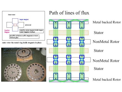
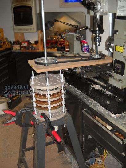
Greetings, I have been working on a new PMA configuration. Must of the work has been developing the fabrication method. I stack the rotors and stators vertically along a central axis. The stator are wired using the 3 phase star configuration. This allows the stators to be connected in parallel. As I add more stators the internal resistances drops and the output increases for the same RPM. I need some help selection the best wire size and number of turns that will produce a high output at a low RPM. I have to purchase more wire, I am trying to improve test results. Comments welcome. Current PMA specs: 4 rotors, 16 magnets per rotor, 1 x ¾ cylinder 3 stators, each stator wired as 3 phase star, 4 coils per phase Coils on stator, 2 in hand, 22 AWG, 100 turns results from bench test: test load, 12 volt deep cell 1 stator, phase resistance = 4.3 ohms Amps____RPM 0.38_____190 2.06_____310 3.8______440 2 stators, phase resistance = 2.4 ohms 0.51_____189 2.6______288 3.8______340 3 stators, phase resistance = 1.9 ohms 0.03_____150 1.56_____186 2.95_____270 6.5______360 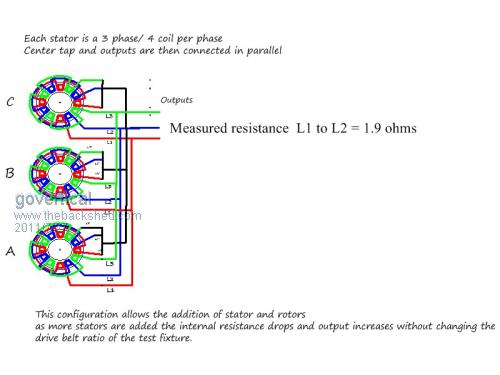
just because your a GURU or forum administer does not mean your always correct :) |
||||
| Greenbelt Guru Joined: 11/01/2009 Location: United StatesPosts: 566 |
govertical; HI, Quite a machine you have here, The following is not meant to discourage you from completing your project , Some times a new look, a different slant on a thing will show a hidden detail. You have made a larger alternator from 3 smaller ones,  with coil phases in parallel you have created an alt. with bigger magnets(flux value) and larger wire (6 in hand) @ one hundred turns, with coil phases in parallel you have created an alt. with bigger magnets(flux value) and larger wire (6 in hand) @ one hundred turns,
I suspect the resistance indicated is due to the test current having parallel paths through the winding coils. Each coil will still have its original resistance. It appears that you have a good handle on mechanical ability and the tools to work with so I'm pretty confident you will work this out with success. I am not one of the forum's expert alternator builders but will offer what little knowledge I have. Generally Voltage is dependent on resistance in the circuit, Current is dependent on the lack of resistance, (Example, A spot welder has an output winding of 1 1/2 to possibly 6 turns.the Voltage less than 6, Current in the thousands of amps. the Voltage in an auto Ignition coil around 16000, and is produced with 14 V. x 1.5 amp = 21 watts. ) The secondary winding in an auto coil has around 1500 turns of hair size wire. The resistance here is quite high. Voltage or amps or both are dependent on the Magnetic Flux density, the coupling of the coil with the Flux, Air gap, Magnetic path and shape. along with turns in the winding and very importantly the speed of the flux passing the coil. 100,000,000 lines of magnetic flux must be cut in one second to produce one volt. EDIT; a typical good magnet with 400,000 lines and having 1 turn on the coil would have to pass the mag. 250 times in 1 second to produce 1 volt. using 100 turns it would need two and one half passes. 150 rpm. The niobium mags have stronger fields This is the reason that no one can tell you how many turns or size of wire will be required for your creation. we Don't know the strength of your mags or how well you have coupled the magnets, don.t know how fast you plan to run your machine or the power source it will use and how much power you would expect or be happy with. Here is advice you will see all over this web site, wind a test coil as Gizmo has done,( see, YET ANOTHER AXIAL, page 3 and 4) (End Edit) in the windmills Forum, Keep doing this until a suitable coil when multiplied by the way you will connect them will have the output you desire. 
Welcome to the forum, have a great Day. Looking forward to see your progress. --------------Cheers, Roe Time has proven that I am blind to the Obvious, some of the above may be True? |
||||
| govertical Guru Joined: 11/12/2008 Location: United StatesPosts: 383 |
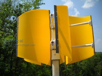
Hi, thank you for the information. I only have basic knowledge of PMA relationships of speed, coils, magnets. Because each stator has 3 inputs and 3 outputs I connected the 3 stators to form a 3 phase star with 12 coils per phase and I was able to get a much higher output at a lower RPM but the internal resistance was 12.6 ohms and must of the power being produced was being consumed due to heat. In the past I only fabricated dual rotors with a fixed internal resistance. I tend to think in terms of relationship and this is turning into a good learning experience. I am planning to use a multi-blade Savonius VAWT to drive the PMA. It has lower RPM but high torque. What would really help is to find a 200 watt dual rotor design then I could adapt the coils and magnets to this stratum configuration and I would be in the ball park. Thanks again for the information, best regards. Comments welcome. 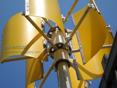
just because your a GURU or forum administer does not mean your always correct :) |
||||
| Greenbelt Guru Joined: 11/01/2009 Location: United StatesPosts: 566 |
govertical Generally Voltage is dependent on resistance in the circuit, Current is dependent on the lack of resistance The above statement is not true.  Sorry ! Sorry !
Voltage is dependent on the number of turns, flux density, speed in the changing value of the magnetic field. the higher the voltage, the greater the number of turns and more wire increases the resistance. ------Cheers, Roe Time has proven that I am blind to the Obvious, some of the above may be True? |
||||
| govertical Guru Joined: 11/12/2008 Location: United StatesPosts: 383 |
Hi, this appears to be one of the beneficial and unforeseen side affects of placing the stators in a stratum formation. I connect the stators in parallel, I am adding more copper using less magnets and the internal resistance decreases. I am casting another stator today and adding it to the existing unit to see if the condition holds true. I will post results when available. Enjoy the day. just because your a GURU or forum administer does not mean your always correct :) |
||||
| govertical Guru Joined: 11/12/2008 Location: United StatesPosts: 383 |
Project update: Connected stator A and B in series, then connected stator C in parallel with A and B internal resistance = 1.9 ohms using 12 volt battery as test load Amps______RPM 0.006______100 1.46_______184 5.0________300 values measured using test fixture Comments welcome, enjoy the day just because your a GURU or forum administer does not mean your always correct :) |
||||
| govertical Guru Joined: 11/12/2008 Location: United StatesPosts: 383 |
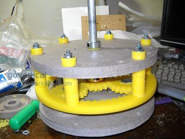
project update,I am adding a gear box, the bolts that mount the planetary gears are not straight and cause cogging. I still have to attach the Ring gear to the blade rotor and run it on the lathe for a few hours. 3:1 ratio. It just might work. Enjoy the day. 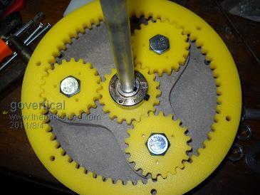
just because your a GURU or forum administer does not mean your always correct :) |
||||
| Tinker Guru Joined: 07/11/2007 Location: AustraliaPosts: 1904 |
Have a look at this site: gear ratio You might be surprise you actually get a 4:1 ratio with these gears if I counted the teeth correctly 
I run a 6.4: 1 planetary gear on my vertical and its been working well, only the planet gears are plastic in mine though. You do have to align the gear shafts correctly, running this set up while its binding anywhere will put excess wear on the teeth, even if just for a lathe test. Have fun  Klaus |
||||
| govertical Guru Joined: 11/12/2008 Location: United StatesPosts: 383 |
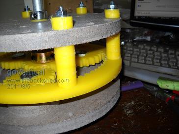
Hi, it is not perfect but for a first attempt it works better I than I accepted. When the ring gear is not installed it spins freely. After the ring gear is installed it binds in one location but stills spins easily. Noise is very low and when installed on top of the PMA all the gear should line up better. It does need some run in time on the lathe. Hopefully I can get it installed and test it over the winter. Enjoy the day. 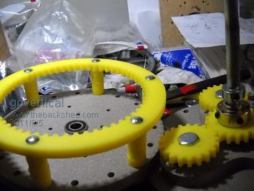
just because your a GURU or forum administer does not mean your always correct :) |
||||
| Gizmo Admin Group Joined: 05/06/2004 Location: AustraliaPosts: 5078 |
Nice looking gears Lauri. Did you CNC those yourself? I've used gearboxes from 4,5 and 9inch angle grinders in the past. They are usually 3:1 to 4:1. Glenn The best time to plant a tree was twenty years ago, the second best time is right now. JAQ |
||||
| govertical Guru Joined: 11/12/2008 Location: United StatesPosts: 383 |
Hi, yes I have a small CNC router. I purchased software that generates the gears and allows me to save the files as .dxf files. Then I use DeskCNC to generate the G-code and I use Kellyware to drive the CNC. After the first road of the VAWT I discovered the blade configuration was very slow. I am adding another stator and rotor and I decreased the pitch of the blades to decrease the surface area of the blades to the head wind. With the addition of the gear box I should get better results. I know now the magnets and coils are not the right size. I am very happy that I was able to verify the PMA configuration does work. It address’s to problem areas of PMA design, internal resistance and required RPMs. The fabrication method I use limit’s the diameter of the PMA I can fabricate. By adding stators and rotors in the vertical configuration I am able to increase the output and reduce the RPM. I am still experimenting with all the configuration but connecting the stators in parallel seem to work best. I just need to find a solid 10 inch dual rotor design that has a established power curve then I can fabricate it using the stratum technique and compare results to see if my theory’s are true. I searched for affordable gears and was not able to find them, your solution is very clever. Enjoy the day. just because your a GURU or forum administer does not mean your always correct :) |
||||
| grub Senior Member Joined: 27/11/2007 Location: AustraliaPosts: 169 |
Lots of washing machines use similar planetary gearing. However the Hoover gearboxes from either the Premier (510 to 710) or the Elites (960 to 2005) have the ring gear similar to what govertical made. Not all have access to cnc :( |
||||
| govertical Guru Joined: 11/12/2008 Location: United StatesPosts: 383 |
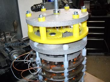
Project update: Installed gear drive on top of PMA. It spins very stiff. I think just from the force needed to spin manually I am going to have to fabricate much larger blades or make a smaller alternator. This is my first attempt using a gear drive, I have no earlier experience to relate it to. Comments welcome. 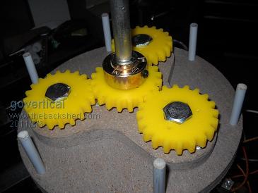
just because your a GURU or forum administer does not mean your always correct :) |
||||
| Tinker Guru Joined: 07/11/2007 Location: AustraliaPosts: 1904 |
So, why does it turn stiffly? is it because of your PMA or is the home built planetary gearbox causing it? FYI, the 6.4:1 planetary gearbox I'm using (its out of a Shibawu sp? washing machine) turns *very* easily the alternator shaft when free wheeling. Of course, once you have your PMA wired for actually generating power, that power has to come from somewhere and you'd feel that if you tried to turn the shaft by hand. What I did is to play with the gearbox on its own first. As you know, there are three ways to use a planetary box, depending which part is held stationary. Since my gearbox is sealed and had a shaft within a shaft at one end I fiddled with it until I worked out which part to lock to get the desired ratio. It was then just a question of mounting it correctly. Klaus |
||||
| govertical Guru Joined: 11/12/2008 Location: United StatesPosts: 383 |
http://www.youtube.com/watch?v=JDMdc07oWpk Hi, just a quick video showing source of noise problem. Thank you for all the help I have been receiving. Enjoy the day http://www.youtube.com/watch?v=JDMdc07oWpk just because your a GURU or forum administer does not mean your always correct :) |
||||
| govertical Guru Joined: 11/12/2008 Location: United StatesPosts: 383 |
Hi, I was able to square and center the planetary gears. It is still not perfect, but it is considerably better then it was. The noise has greatly been reduce. I have to slow down the feed rate on the CNC the next time I cut a set of gears to get them more centered. I changed the blade angle on the blade rotor. It spins more freely now, much less drag. I am planning on another road test this week and I will post results when available. What size blade should I use for a 500 watt output at 25 MPH (35 km/h) wind speed? I am planning to use the same fabrication method I am using know, it works really well for me. I just need to find the correct size blades. just because your a GURU or forum administer does not mean your always correct :) |
||||
| govertical Guru Joined: 11/12/2008 Location: United StatesPosts: 383 |
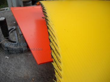
Road test with skid marks Result of today’s road test. Using TV antenna hardware was not a good idea, the mast bent at 65 MPH and the turbine hit the road and was dragged a short distance. I was testing the 6 blade configuration without gear box. The deceased blade angle did improve RPM’s, cut in at 35 MPH. Results indicate that PMA needs larger magnets, thinner stator coils and larger blades to drive gear box. PMA appears unharmed but I am still assessing the damage. Enjoy the day. 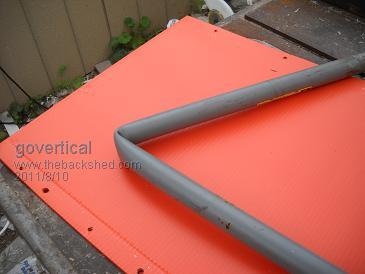
just because your a GURU or forum administer does not mean your always correct :) |
||||
| govertical Guru Joined: 11/12/2008 Location: United StatesPosts: 383 |
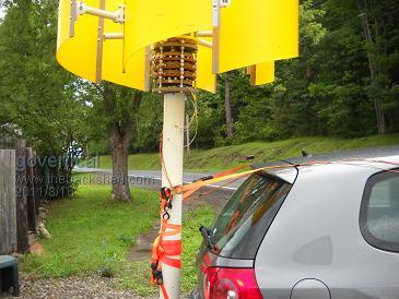
Road test results with 1:3 gear drive added, using 12volt deep cell as load: MPH________DC amps 10__________0.05 15__________0.5 20__________2.6 25__________3.7 30__________4.0 35__________4.5 40__________5.0 The meter display was not stable, The data is just ball park. The highest reading was 6.53 amps @ 40 MPH, probably cause by cross winds. Not the best numbers posted but it is a start. Data gathered today can be used to judge the value of future modification. Enjoy the day 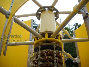
just because your a GURU or forum administer does not mean your always correct :) |
||||
| Gizmo Admin Group Joined: 05/06/2004 Location: AustraliaPosts: 5078 |
65MPH might be expecting a bit much from any hardware, thats the sort of wind speed that will see a lot of turbines come crashing down. Anything over 40MPH and a windmill should be going into survival mode, like furling or shutting down in some way. Looking at the pictures, its only a small turbine, so your figures might actually be good. What is the height and diameter of the VAWT, from that we can work out how much power could be expected. Very professional looking work. Glenn The best time to plant a tree was twenty years ago, the second best time is right now. JAQ |
||||
| govertical Guru Joined: 11/12/2008 Location: United StatesPosts: 383 |
Hi, when I was taking the VAWT off the car I noticed that I neglected to install a required bearing on the top blade rotor, when installed the blades should spin better. Thank you for offering to help, I have very little knowledge regarding the mathematical formulas used, I just understand some of the basic relationships. 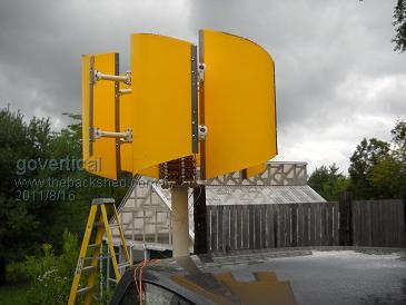
just because your a GURU or forum administer does not mean your always correct :) |
||||
| Page 1 of 9 |
|||||