
|

|
Forum Index : Windmills : New wing build
| Page 1 of 4 |
|||||
| Author | Message | ||||
| Air Bender Senior Member Joined: 25/01/2011 Location: AustraliaPosts: 206 |
HI all I have finaly started a bigger wing build having pushed a few other projects aside for now. We have only had light winds for the last couple of weeks and the mill has not been making much power, which has got me going. The new wings are being built out of cedar weather boards, I chose cedar as they should weather very well. They are 2m high twice the hight as my old ones and they have a cord width of 14cm. 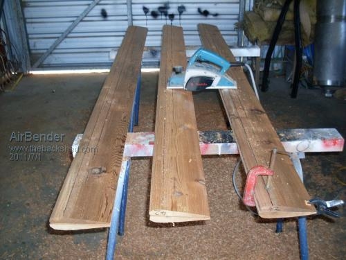
Each wing is made of two weatherboards that i plan to stick together with liquid nails and a few wood screws. But before i stick them together i plan to hollow out the inside, apart from where the mounting points are to lighten them up as much as possible, as i am doing this i will start to weigh them they so i can get a good balance. 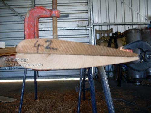
The profile has been roughed out. Hopfully tomorow I can get the sander out and finnish the profile off. 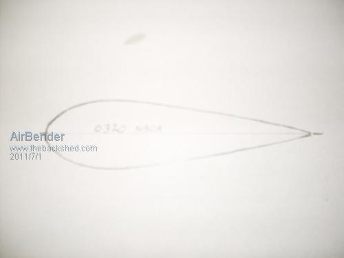
The profile I have drawn up I have calculated to be a 0020 naca. Which i hope will give me good start up and low to moderate wind performance. I plan to run it with 0 deg AOA, but as we know our best layed plans can change. 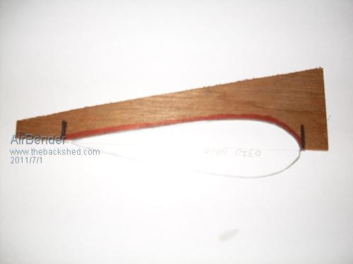
I have just made up a plywood profil stencil to use while sanding them. I think i will need to beef up the rotor arms a bit. I think these wings will realy try out the structure of the rest of the mill. I will try to keep you updated with this build as it progress. All the best Dean. |
||||
| Tinker Guru Joined: 07/11/2007 Location: AustraliaPosts: 1904 |
Dean, me thinks you might be pushing your luck too far by using "liquid nails and a few wood screws". Especially so if you are removing much bonding area by hollowing the laminate. For this job I would use nothing less than epoxy glue to stick the laminate together, this has the added advantage that no wood screws (potential water ingress) are required. In an earlier tread the centrifugal forces on windmill blades was explained very well, it might be a good idea to look it up and see what your blades have to hold up against. I would also coat the whole finished blade with epoxy to seal it before painting it to protect the epoxy from UV rays. The old motto 'if a job is worth doing one ought to do it well' comes to mind, especially when potential missiles are created. Klaus |
||||
| Rastus Guru Joined: 29/10/2010 Location: AustraliaPosts: 301 |
Hi Dean, Your choice of weather boards works well for the profile you've chosen,with less work needed to shape them.Top marks.I'm interested to see how weight shedding cavities will change there overall integrity & characteristics.As a side point I've found liquid nails can soften in summer when exsposed to direct sunlight over exstended periods,however that could be location dependant and given the blades will be moving and produce some cooling it may work in your favor because the bond does provide some flex.We will learn a few things along the way with you,Cheers Rastus see Rastus graduate advise generously |
||||
| Air Bender Senior Member Joined: 25/01/2011 Location: AustraliaPosts: 206 |
Thanks Tinker I think you are right, I used epoxy on my last wings and for each wing I glued eight peices of wood together, and they have shown no signs of deteriation on these joins. It is just that these wings are a lot bigger and i was thinking of the dollars. But i think a bit extra spent now will be worth it in the long run. So I will have to get a tin of that good marine epoxy. Also at the fastening points i plan to bolt through both laminates and use big body washers this should help to keep it together as well. All the best Dean. |
||||
| Air Bender Senior Member Joined: 25/01/2011 Location: AustraliaPosts: 206 |
Hi all I beleive i have miscalculated the naca, after recalculating I came up with 0028. All the best Dean. |
||||
| Air Bender Senior Member Joined: 25/01/2011 Location: AustraliaPosts: 206 |
Hi Rastus I realy do like liquid nails, i think it is the best value for money glue you can buy. You can just about fix any thing with it. I put it right up there with duct tape and cable ties, I found it will glue some plastics that most other glues wont. But i think epoxy is better wood glue. I got two wings sanded today, only one more to go. 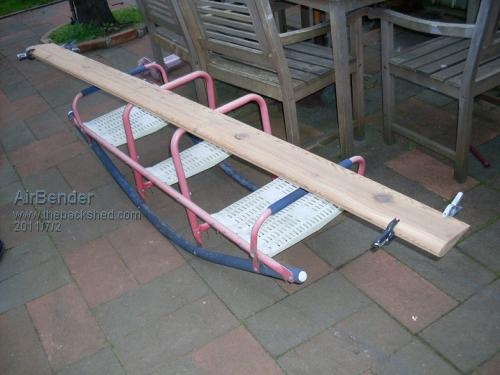
I am back at work tomorrow for 4 days but then i get 4 days of, so i will be able to get stuck back int it then. All the best Dean. |
||||
| Tinker Guru Joined: 07/11/2007 Location: AustraliaPosts: 1904 |
Dean, if you buy that stuff in a 'tin' you probably but the expensive brand 
There are quite a few suitable marine epoxies around and their prices can vary a lot. One of the easier (and cheaper) ones is BoteCote which has a handy 2:1 mix ratio. It comes in simple plastic bottles from 0.75 liter quantities up and keeps for years unmixed, if you keep them sealed and out of the sunlight. To make a glue of it you must mix in the fortifying powder - do that always after you first mixed the 2 part resin thoroughly. You get the very best bond if you coat the glue join first with the mixed straight epoxy, let it seep in a few minutes and follow with the thickened fortified glue mix. I built a 26' yacht that way and its a very strong construction method. Epoxy is also gap filling and much better at that job than liquid nails ever will be. You also mentioned earlier that you liked the 'weathered look' of cedar. Keep in mind that with wood and weather one gets warping if the wood is left outdoors exposed to the elements. So do coat it but then consider if you go for a 'bright' finish - the wood is visible through the coating - then you also get a much higher maintenance regime in the bargain. Paint it with a good quality paint and it lasts much longer up there. Klaus |
||||
| vawtwindy Newbie Joined: 23/10/2010 Location: IndiaPosts: 31 |
All the best dean, Looks similar to GOE222, is that right? |
||||
| Air Bender Senior Member Joined: 25/01/2011 Location: AustraliaPosts: 206 |
Thanks Tinker, I have built two sailing boats using the west system and helped out with few more, the last one i built is 14 foot long and is now 30 years old and is hanging in the roof of my shed , I am at work at the moment otherwise i would post a picture of it. But this was a while back so a am not realy up with whats on the market today. I like the idea of puting on the straight epoxy first for maximum penetration. What was ment by good weathering is if water does penetrate into the wood, cedar has a good resistance, i always did plan to paint them. All the best Dean. |
||||
| Air Bender Senior Member Joined: 25/01/2011 Location: AustraliaPosts: 206 |
Hi vawtwindy It is a bit diferent to the GOE222 which is not symetrical. First i drew up what I thought looked good, then i looked around on the net for similar profiles and how they perform for confermation. One place I looked in was Smithys link to fluid modelling, which i am not shore how acurate the simulation is to real life but it did get me in. The one on the link that i found closest to mine is the Remkick 5 which seemed to have good perforance in the areas i was looking for. Mine is not an exact copy of this it but looks similar. All the best Dean. |
||||
Bryan1 Guru Joined: 22/02/2006 Location: AustraliaPosts: 1344 |
G'day Dean, I found this site was great for looking at different wing profiles. The link shows the GEO222 but it take out the 435 in the header then you can search for just about any profile. Cheers Bryan |
||||
| Air Bender Senior Member Joined: 25/01/2011 Location: AustraliaPosts: 206 |
Hi all I have been trying to work out what diameter i should put these wings at. I was originaly thinking at 2m or under as i thought that smaller the diameter the more RPMs. But i have been doing a bit of reserch, which always gives me a sore head becouse everything contradicts everything else. Anyway i have come across the solidiry factor, which is new to me but maybe not to others here, aparently if you bring your diameter in to small it can reduce your RPMs which does make sense becouse if you bring your wings in to close together they will start to gas each other. From what i read a solidity of .35 is good and to work out the figure you add all your wing cords together and then divide it by the radius, so i worked out three cords of 14 cm, to have a solidity of .35 the radius needs to be 1.2 m, A bit more than what i origanaly thought but if that is where i will get the best RPMs thats where ill go. All the Best Dean. |
||||
| smithy Regular Member Joined: 30/01/2011 Location: AustraliaPosts: 52 |
Depending on local govt regulation I would lean towards a taller thinner unit, as it will generate more RPM for wind swept area, whilst a shorter wider unit will generate more torque but less rpm. It really depends on which alt you want to use and what is its sweet spot wrt RPM and Power output. Solidity is useful as a higher solidity will give you better self starting characteristics. Over all somewhere between 0.3 to 0.5 is likely to be OK, but again it all depends on your alt. Smithy "The answer my friend is blowing in the wind, the answer is blowing in the wind" Bob Dylan |
||||
| Air Bender Senior Member Joined: 25/01/2011 Location: AustraliaPosts: 206 |
Hi Smithy I have found there is a big variation in the way that solidity is calculated, it should be just % of wept area. The most common formula I found is Nc/R but i have also seen, Number of wings x cord divided by diameter and a few more veriations. I have gone with the one from the sites that seem to be a bit more scientific which is the first one i posted, this gives me a radius of 1.2m and a diameter of 2.4m, with my wing hight of 2m that seems about right. All the best Dean |
||||
| electrondady1 Senior Member Joined: 12/02/2009 Location: CanadaPosts: 208 |
rather than depend on someones calculation it might be prudent to build in the ability to shorten or lengthen the horizontal support arms. to allow you to find the optimal solidity for your particular wings. as well,an adjustable angle of attack would be handy . just thinking the aoa would change as the diameter of the mill changes. |
||||
| Air Bender Senior Member Joined: 25/01/2011 Location: AustraliaPosts: 206 |
Hi electrondady1 I think you have put me on the right track here my thinking is a diameter somewhere between 2 to 2.5m so I should go for the largest diameter first as it will be easyer to shorten than to lengthen. On my original mill I did make it adjustable but I see it as a patental weakness as these wings are twice as big and a lot heavier. So if i need to reduce the diameter i will have to cut and rebolt. All the best Dean. |
||||
| Air Bender Senior Member Joined: 25/01/2011 Location: AustraliaPosts: 206 |
Hi all I have just done a complete turn around on the diameter of the mill and gone back to the my original idea of having it under 2m, and that is final as i have cut the steel for the rotor arms. What I posted earlyer that the aoa would be 0 deg may be a little misleading as the way i look at aoa is the angle of the trailing edge to the swept circle of the wing. I think this is more importent than the aoa of the leading edge which is roundish and will take a range of wind angles coming into it. The small wings I have up know are very ajustable and after playing aroun with them i found 0 deg aoa on the trailing edge to be to best setting for combination for startup and general performance. I worked this out today for my wings to obtain the 0 deg on the trailing edge I need to set the centre line of the profile at 92 deg from the rotor arm, this has the leading edge slightly angled out. Decreasing the diameter, lenthing the cord or moving the mounting point forward on the profile, will increase the the centre line of the profile to the rotor arm angle to retain 0 deg aoa at the trailing edge. I am not saying that this is the correct way to do it, it is just the Airbender theory on aoa. We had a severe wind warning the other day, having the battery fully charged I was tempted to tilt the mill down. but as I have a new build on the go, I left it up. An SES guy told me they were geting gusts of 160 km/h down at the coast, Im shore we didnt get them that strong but they still howled through pretty hard. The mill held together ok annd didnt realy spin up much harder than normal. So i think it was the loading on the F/P that kept the speed in check. I think it would have been a different story if the battery had have been disconacted. All the best Dean |
||||
| smithy Regular Member Joined: 30/01/2011 Location: AustraliaPosts: 52 |
Air Bender, I think you will find the Remkick 5 blade is one that Itsandbits came up with, he sometimes posts on this site. He would probably be happy someone else is using his Blade. Your AOA by the definition I use, would be 2 degrees, as its the angle between a line linking leading edge and the trailing edge, and a circumference line of the arc of the VAWT. Smithy "The answer my friend is blowing in the wind, the answer is blowing in the wind" Bob Dylan |
||||
| Air Bender Senior Member Joined: 25/01/2011 Location: AustraliaPosts: 206 |
Hi Smithy I have found there is quite a few different ways of coming up with certain definitions when it comes to vawts which makes it hard to share information at times. I think you will find there is a fair bit of difference between the Remkick 5 profile and mine and i am shore Itsandbits would agree, it is just that of all the other profiles i have seen on vawts, his is the most similar in dimention but i am shore there is a few more out there that i have not seen. The wings i have on my mill at the moment have 2 elements which enable the camber to be ajustable, so i have taken this into consideration when i drew up the profile. This profile hopfully will be good for pushing the FP but may not be as good on other alternators, and I doubt that i have it right yet. Murphy would confirm this. So i woulnt be surprised if there is another wing build down the track. I have sanded the last wind and have the steel for modifications I am doing to the mill structure. 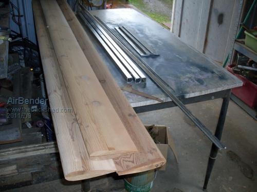
I plan to still use the original rotor hub but every thing above it will be replaced. The hub has a lenth of pipe that fits over the original F/P shaft ond has sleaves fitted at the top and bottom to make it a very neat fit on the shaft. On top of the pipe I have welded a milk pipe nut which has 5 sides to which I have welded 10mm plate for the rotor arm mounts, and to thest i have braces welded domn the the pipe. In side the pipe nut i have fitted plastic spline out of the original wash tub. 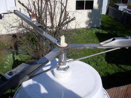
I took this picture when i was measuring up the the diameter. 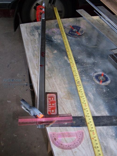
This is how i worked my AOA. All the best Dean. |
||||
| Air Bender Senior Member Joined: 25/01/2011 Location: AustraliaPosts: 206 |
I am just correcting my last post The milk nut on the hub has 6 sides not 5. All the best Dean. |
||||
| Page 1 of 4 |
|||||