|

|
Forum Index : Windmills : Measuring cogg
| Page 1 of 5 |
|||||
| Author | Message | ||||
| Highlander Senior Member Joined: 03/10/2006 Location: AustraliaPosts: 266 |
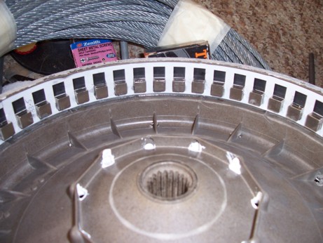
HI all, I did a neo conversion 7p2p with 10mm by 10mm 3mm thick magnets, set two high giving a gap of around .5mm So far I have only 1 line in place. I was considering a second staggered line. It coggs less than the 3 phase ferrite but output was only 20 amps without grinding the stator and 17.5amps decogged. I think we all need to measure the cogg with a test which can be replicated by everyone. I emailed this to Glenn but I can't see it on the site yet so here it is. Set the frame in a vice, wrap some string 2 times around the magnet rotor, tie on a 2litre bottle cut in half and pour in water till it starts to spin from a still start (I saw this on a website) To measure the running resistance do the same thing but give the rotor a push start, keep taking out water still it stops spinning. Take 5 tests and average them out. I did it with the 3 phase and: still start was 821 ml running was 245ml This unit gives out 17.5 amps (decogged) the 7 phase with one line of neo's standard stator: still start 720 ml running 245 ml This unit gave 20 amps I decogged the 7 phase then still start 675ml running 245 ml This unit gave 17.5 amps (2.5 amp loss decogged) It would be interesting to see how the factory 7 phase magnets compare. It's a crude test but it will give us some ballpark numbers. I would probably be better to weigh the water as it can vary in weight. The output was measured with a 900 watt ryobi drill in 1st gear connected to a 16mm spark plug socket via bolted on all thread It appeared to be around 400-500rpm. 
 Central Victorian highlands |
||||
| Gizmo Admin Group Joined: 05/06/2004 Location: AustraliaPosts: 5078 |
Hey Highlander. Yeah I was getting there, got a bit on at the moment. Folks I think this is a great little trick to measure cogging, should be very accurate. When my new 48 magnet hub gets here I'll do this test to see the difference between it and the older 56 magnet hubs. Glenn The best time to plant a tree was twenty years ago, the second best time is right now. JAQ |
||||
| clarence Regular Member Joined: 27/10/2006 Location: Posts: 63 |
Great stuff Highlander! I will do a water test on my conversion today. are you going to do some tests with staggering/offsetting the next layer of magnets? I would be really interested to see what that does to the cogging and performance. |
||||
| clarence Regular Member Joined: 27/10/2006 Location: Posts: 63 |
I did the water test and I think my conversion is a bit of a cogger. oh well. [20mmx10mmx3mm neo's 48 mags 7 phase]. 1670 ml, nearly 1.7 kg still start. 550 ml, just over 1/2 kg running. I could have sworn the original rotor cogged more, but maybe not. |
||||
RifRaf Newbie Joined: 15/10/2006 Location: AustraliaPosts: 32 |
bloody awesome idea, only had one millhead in vice so these are results for 3 Phase F&P with standard magnet hub and no load connected. Tested using 2 litre milk bottle and weighing bottle after. Still Start 1100g running start 300g Will put the new magnet up on same motor when i get home and then test the 7 phase. |
||||
| Highlander Senior Member Joined: 03/10/2006 Location: AustraliaPosts: 266 |
Hi Guys, those measurements are pretty high. I was winding the string around the rim of the magnet rotor, were you winding it on the plastic locking nut in the centre? Maybe we all need to take out our stators and measure just the bearing drag to compare, perhaps there may be problems there. I would have thought the 3 phase with ferrite rotor would be very similar however mine was decogged but it shouldn't make that much difference. Central Victorian highlands |
||||
| Highlander Senior Member Joined: 03/10/2006 Location: AustraliaPosts: 266 |
Clarence, sorry mate I forgot to answer your question about the magnets. I was thinking about that and if I did stagger them it may defeat the purpose of going down to 48 magnets, because 1 in 7 are lined up with the 7 phase but if they are staggered it may end up being 2 of 7 lined up which would cogg BIG TIME. Perhaps a small stagger is worth a try, only my sanity to lose.  Central Victorian highlands |
||||
| clarence Regular Member Joined: 27/10/2006 Location: Posts: 63 |
Hi highlander, It shouldn't be a problem, each staggered magnet pole is only widening the field a bit for each pole. the efficiency may drop because of the lack of magnet material missing from top and bottom magnets, but it should be a good guide regarding cogging. re the water experiment. I was thinking my results were a bit extreme compared to yours.. so here are the figures. my rotor is 270 mm outside diametre with the string around the outside diametre, not the centre cog. |
||||
| Highlander Senior Member Joined: 03/10/2006 Location: AustraliaPosts: 266 |
Hey Clarence, yeah this magnet thing has got me confused, I need to read that chalko report a few times. Re water test the F&P rotor is about the same size as your brake drum, but don't forget that your magnets are twice as big as mine. So if you double my neo measurement of 720 mm to 1440ml that's 230ml difference. How freely do your bearings spin? And how accurately did you install the magnets? They need to be spot on so I'm told. I'd be interested to see what amps yours produces at 400-500rpm, try and drive it with a drill. Central Victorian highlands |
||||
| clarence Regular Member Joined: 27/10/2006 Location: Posts: 63 |
well, my bearings spin perfectly freely, but I am really sorry, but my readings are compromised due to the fact that I machined 1 mm or more off my stator. and now due to the reduced thickness of the stator teeth all is not certain. there is a mention of this in "neo conversion" on this site. fantastic idea Highlander. this makes it very easy to compare stators. |
||||
RifRaf Newbie Joined: 15/10/2006 Location: AustraliaPosts: 32 |
Ok have tested a 3 phase winding that produces power fine, tested in a vice with some garden twine tied in a loop around the rotor outside edge, the biggest OD, and then wound around a few revolutions before hanging a 2 litre plastic milk carton from it, filled from another bottle until result, then did a few times. Old Rotor, standing start 1100g , spinning start 300g New Rotor, standing start 400g , spinning start 375g While the cogging is gone the spin with the new rotor could only be described as a slow chug chug while when the old rotor overcame its resistance the bottle dropped down fast. it does however show that there is more resistance for me. The output power with new rotor has not been near old one with 3 phase but yet to have decent wind for testing more. |
||||
| Highlander Senior Member Joined: 03/10/2006 Location: AustraliaPosts: 266 |
Hi guys, let me just clarify it wasn't my idea. I saw it on a website and a guy at a re shop told me about it as well. I found out since, renew magazine did testing on F&P similar to this. To keep all out all other variables make sure these tests are done with no props or or prop hub in place and the string is wound around the largest part of the magnet rotor. RifRaf, those numbers on the new 7phase look great  running resistance is surprise though. running resistance is surprise though.
If we get a few others to do this test we should see a pattern forming and if someones is well over this could help to diagnose any other issues and vice versa. Good work guys Central Victorian highlands |
||||
| clarence Regular Member Joined: 27/10/2006 Location: Posts: 63 |
Hey Highlander, I would only stagger the top magnet 1mm for a start, so that the overall magnet width becomes 12mm in your case. I wish I had bought 10mm square mags like yours so I could experiment a bit. warning, I am only a noob at all this, and it may not work, but worth a try I reckon.  |
||||
| Highlander Senior Member Joined: 03/10/2006 Location: AustraliaPosts: 266 |
Hey Clarence, not a bad idea. With yours I thought you might try placing them on a angle similar to the one Matt Lyons did for Brucedownunder. You'll need a template to do this. I did one for mine and it worked well, as you can see from the pic mine are vertical but changing the file to angle them shouldn't be too hard. I was going to run it out to film which is more accurate but the test one I did on the plan printer worked pretty well, so I don't think film is needed. Go to the webpage and look at article,readers windmills, Matt has some pics there. I got my magnets from frenergy in brisbane 47cents each. BTW where in oz are you? I'm in central highlands near Yea, bloody windy here all the time, throws my long distance shots off, but good for a mill.  Central Victorian highlands |
||||
| clarence Regular Member Joined: 27/10/2006 Location: Posts: 63 |
thanks for that Highlander. yep I reckon I can angle my mags. I can see why you are called Highlander, my brother used to live up there in a place called caveat. really hilly. I know the area well. I am near Horsham western vic. I got my neo's from the same place. |
||||
| Megawatt Man Senior Member Joined: 03/05/2006 Location: AustraliaPosts: 119 |
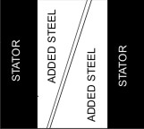
G'day gentlemen. This is a bit of basic electrical machine theory. So far I have never seen a F&P unit, so what I am about to say may not work. Instead of staggering the neos to reduce cogging, another approach may be to extend the poles with magnetic pole pieces on the stator. A flat piece of mild steel would be fitted to each pole in such away that adjacent pieces almost meet around the circumference. The adjacent edges would be skewed, so that the magnets encounter the pole piece of the next pole before they leave the last. This is a very common technique used in many electrical machines to reduce noise and cogging. Where I just don't know what I'm talking about is that I don't know whether a pole piece could be fitted to the pole tops - I just don't know how much space there is from the top of the coil former to the extremeity of the pole. Assuming there is space, it would need a lot of careful work. Laser cutting would be essential to achieve a very good fit. The pole pieces would need to be fitted, possibly shrunk on so that they could not come off and break the machine. They probably would need to be tacked on with a bit of MIG and the weld carefully ground off. What about that Gizmo? Megawatt Man |
||||
| Highlander Senior Member Joined: 03/10/2006 Location: AustraliaPosts: 266 |
Hey Megawatt, I think I know what your saying is my drawing close? 
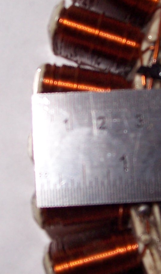
here's a close up of the stator 90 deg to drawing 
. the second pic's a bit blurry like my vision on a saturday night 
The metal protrudes only 1mm from the plastic former, the plastic could be filed back but the windings are only 2mm away. Looks like a great idea but jeeeeeeeezzz a lot of work, with very precise tools req'd. Well beyond my skills and farm tools. I appreciate the reply though. 
Central Victorian highlands |
||||
| Megawatt Man Senior Member Joined: 03/05/2006 Location: AustraliaPosts: 119 |
Yes, Highlander, that's what I'm talking about. You see, cogging is just an indicator that a very good magnetic coupling is taking place. And this means more power output, if you can only get the machine started against the cogging forces. Now the arrangement I am suggesting will not reduce the magnetic coupling effect, but there will be some rotation where the cogging effect is somewhat smoothed because of the skewing. I am working on Dr Chalka's paper and as I see it, most people on this site are interested in more power, not less. Neverheless, what the Doctor says is correct and we only need to apply his arguments in reverse, to achieve more power out, not less. My immedate gut feel to the concept of reducing the number of active poles is - why not just make two windings of those already there and have two alternators operating on the same shaft but in parallel? And yes, it is a big ask to make all those pole pieces, that's why I directed my question to Gizmo, who has expertise and experience in laser cutting. In the end, my suggestion would need a production line process to make dozens of bits that could just be driven on and probably welded. A bit more about cogging with F&Ps. They are a stepper motor, and when used in position contol applications, stepper motors just cog! You change polarity of all the poes and the magnets in the rotor cause it to step to the next position in which the electro magnets of the stator match the permanent magnets of the rotor. It steps in fixed increments - cogging is it's middle name. And F&P engineers have spent many hours of calculation, design and experimentation to bring about a motor that is the best compromise they can create beween efficiency, power, cost, noise and no doubt, durability. So for me, who wants about 1 kW clear from these devices, I reckon I just have to put up with cogging. I further reckon that my other gut feelings that an advanced VAWT is going to be needed to deliver me what I want - along with neos, a brake drum for a rotor and not much clearance between rotor and stator. But gut feel is a bit suspect, so I like I said above, I'm working on Dr Chalka's paper. Megawatt Man |
||||
| clarence Regular Member Joined: 27/10/2006 Location: Posts: 63 |
or what about using something like a big sprocket with 48 teeth on the front of the rotor and a really strong neo or several neo's that lines up with the sproket teeth halfway between cogs? if that makes any sense. |
||||
| Highlander Senior Member Joined: 03/10/2006 Location: AustraliaPosts: 266 |
Hi Megawatt, I was having a think about that and it probably wouldn't be that hard after all. If you look at the drawing the plates (in red) would actually be the same, just replicated all the way around. They would need to be curved, so have the parts lasercut and bent with a press then mig them on, the only part I can do is the mig. 
There's not much space in there to add a plate probably 1mm. Plates that size would be attracted to the neo's and more than likely bend upwards and scrape the magnets. However you could make them thicker and use different magnets, have a look at my rotor, they are 3mm thick set two high you could just use 1 or a 4mm magnet etc. Or as you said use a brake drum. I think your right directing this to Glenn. Glenn how hard would this be?  Central Victorian highlands |
||||
| Page 1 of 5 |
|||||