|

|
Forum Index : Windmills : Using Altonís Blade Calculator
| Author | Message | ||||
MacGyver Guru Joined: 12/05/2009 Location: United StatesPosts: 1329 |
Crew Does anyone have any experience using Alton's Blade Calculator with blade stand-offs? What I mean by 'stand-off' is merely extending the blade spar out from center, which means at the hub area, there are only posts sticking out into the breeze with the respective blade root not actually coming into play for whatever distance it is held off the hub. I'm wondering if there's more the amount of power one can extract from a given blade diameter than meets the eye and if there is any "threshold" blade surface necessary or if one could fly a tiny blade ten feet out on a tube and have a functional 20-foot diameter prop. My hunch is it wouldn't work that easily, but I don't really know why. Just curious. . . . . . . Mac Nothing difficult is ever easy! Perhaps better stated in the words of Morgan Freeman, "Where there is no struggle, there is no progress!" Copeville, Texas |
||||
Downwind Guru Joined: 09/09/2009 Location: AustraliaPosts: 2333 |
From what i understand the starting torque is generated by in near the hub and the blade speed is generated out at the tips, so it is a balance of the two areas to give best results without causing excess drag. So your theory of a tiny blade out on the tip of a pole would have huge problems with getting started but once (if) going would spin fast. Pete. Sometimes it just works |
||||
| VK4AYQ Guru Joined: 02/12/2009 Location: AustraliaPosts: 2539 |
Hi Mack On a turbine most of the power is generated on the outer 30% of the blade so to a point, extending the blade further out will help, but it does cause the blade to run slower as the tip speed ratio is trying to increase, this depends a lot on the blade design as fast blades have optimized airfoil sections, not so easy to reproduce in our home made designs. There is also another factor that comes into play and that is the Reynolds number of the combination, this is a relationship of the cord of the blade and the airspeed of the blade at its optimum TSR. This governs the lift produced by the airfoil, and that in turn gives the torque produced by the blade, this is also another reason why the outer portion of the blade does the most work as it has a higher Reynolds number. As Pete said the inner part is to get it going and the outer part does the work. As most of our blades operate over a wide range of speeds, the trick is to use the best mid speed blade as the speed increases there is power to burn so no need to optimize the top end unless you are a wind farm developer. All the best Bob Foolin Around |
||||
| aorn318 Newbie Joined: 05/09/2010 Location: AustraliaPosts: 20 |
Hi Mac only new here but i had a read of the "understanding swept area" in projects and information not sure if its what your looking for but it shows how the blades operate and where they generate what % of power Aron If it ain't broke don't fix it |
||||
MacGyver Guru Joined: 12/05/2009 Location: United StatesPosts: 1329 |
[Quote=VK4AYQ] . . . the outer portion of the blade does the most work as it has a higher Reynolds number. Hmmm . . . I thought it was the other way around. I always thought that had to do with surface area and I purposely reduce the Reynolds number on my blade tips by tapering each blade from the root to the tip, thinking the relative speed is greater at the tip and a higher R # means more drag. Do I have it wrong? If I do, it wouldn't be the first time I've goofed up the engineering, by the way. 
. . . . . Mac Nothing difficult is ever easy! Perhaps better stated in the words of Morgan Freeman, "Where there is no struggle, there is no progress!" Copeville, Texas |
||||
niall1 Senior Member Joined: 20/11/2008 Location: IrelandPosts: 331 |
hi Mac a while back i did try Altons calculator ...(apart from the ideal big root angle) i,m not sure if you mean extending the blades or eliminating the inner section ... 
i think if the roots were trimmed a bit and blade extenders were used the drop angles at each station would be confused a bit ..the tsr would be different as was mentioned before and the blade sections wouldn't be as well matched to the swept area they rotate through ...plus you'd miss out on a nice big mounting area to secure them together and onto an alt niall |
||||
| Gizmo Admin Group Joined: 05/06/2004 Location: AustraliaPosts: 5078 |
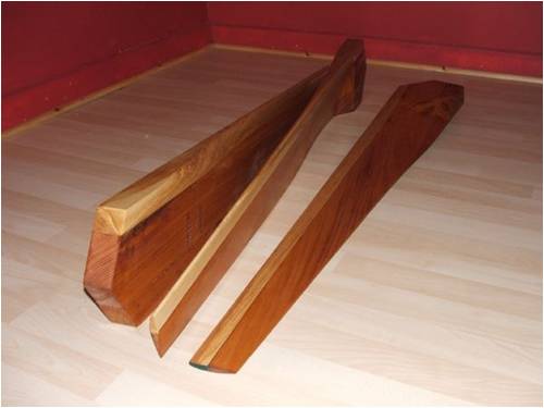
This is the page Aron was refering to. http://www.thebackshed.com/windmill/articles/SweptAreaofHAWT .asp Basically, the inner 1/3 of the blade is only making 10% of your power, and the outer 1/3 is making over 50%. Your better off extending the blades out slightly than spending too much time on the inner 1/3 of the blade. Glenn ps. Nice set of blades there naill The best time to plant a tree was twenty years ago, the second best time is right now. JAQ |
||||
| VK4AYQ Guru Joined: 02/12/2009 Location: AustraliaPosts: 2539 |
Hi Mack The higher the Reynolds number the greater the lift from the airfoil relative to its size so for our application we want torque to drive the generator so it a bit opposite to an aircraft that operates its airfoils at a much lower coefficient of lift to reduce the drag whereas we operate ours at a higher coefficient of lift to increase the rotational torque to extract power from the wind. A twisted blade as in the Alton calculator, that is more pitch accurate over the blade length is theoretically better but due to the reduced cord at the tip it doesn't produce as much torque at slow speeds, this kind of blade is designed for better high speed efficiency. The blades I am using on the new mill arn't twisted to compensate so will be less efficient at high speed but better at low speed and that's where our mills operate most of the time. Its all a compromise as our application is opposite to the use as in aircraft propeller design as a lot of wind turbines are based on. All the best Bob Foolin Around |
||||
| VK4AYQ Guru Joined: 02/12/2009 Location: AustraliaPosts: 2539 |
Hi Mack Just had a look at Altons calculator and compared it to the non twisted blade on my new mill. If you enter 2.8 meter diameter TSR 7 Angle of attack 8 and a coefficient of lift at .8 as that corresponds to the CL of .8 for a Clark Y airfoil section and then look at the carving table angle at each station you will find that the outer four stations are negative angles of attack this corresponds to a lower CL and less power being produced at these stations, this translates to lower torque to the generator compared to a fixed angle of attack of a non twisted blade. The non twisted suffers the effect in reverse as the AA decreases in efficiency as you go closer to the center, a compromise for sure but on slow speed turbines like ours it fills the bill. On huge power generating wind farm machines the blades are designed for the maximum power absorbency over the disk area, this sort of technology is beyond the scope of our small turbines. The blades on my turbine are designed specifically for low speed high lift with a CL in excess of 1 at eight degrees AA and this goes right to the tip of the blade so the force acting through the hub has a greater moment arm for the wind energy absorbed, and so generates more torque, which in turn means more power out of the alternator. It also demonstrated that Altons calculator isnt an absolute for all types of blades but a good indication of energy available within the disk area. All the best Bob Foolin Around |
||||