
|

|
Forum Index : Windmills : Starting the Ceiling fan Windmill!
| Page 1 of 2 |
|||||
| Author | Message | ||||
| arpolis Newbie Joined: 04/08/2010 Location: United StatesPosts: 26 |
Hello to the masses. As a starter project into my windmill making endeavors, I thought I would try my hand at a ceiling fan and converting it for wind power. I understand that what I want to do will take countless man hours of tedious re-winding and several curse words due to things not working right.... But thatís the fun part! Here I have a dissembled ceiling fan I picked up for 10 bucks at our local Habitat for Humanities location. Nine poles for the high and low speeds so 18 in total. I think that makes it easy to re-wire this for a 3 phase 24v system. I think I will just re-wire the magnet wire with several in hand to reduce the turn count. Now I am not on the up and up for ceiling fans so here is where I am at and stopped after the total 10 min of work I am into this. On the "Top" portion of the ceiling fan housing there is this metal ring stuck in the housing that originally went around all the poles. From what I see I think that needs to come out and that is where magnets will go. I just need to figure out how that comes out whether it needs to be cut or its pressure fitted like the two pieces of the housing where. Any thoughts or comments welcomed. More to come....... 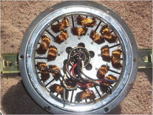
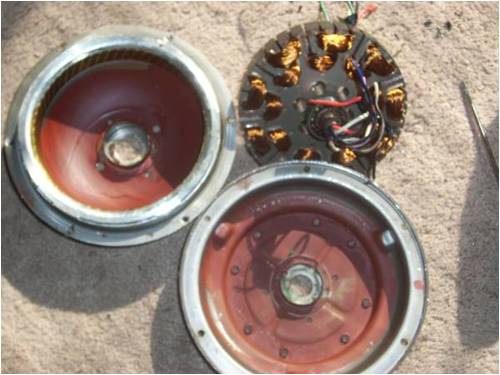
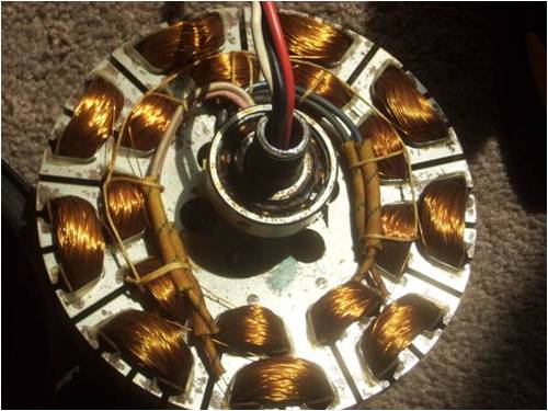
Will it work? Well lick your fingers and touch the two leeds. PZZZZZZZT |
||||
| arpolis Newbie Joined: 04/08/2010 Location: United StatesPosts: 26 |
Yay another step towards being done. Pink and black wires are the outside set of coils and the blue and off white are the inner coils. there is also a set of red, black and white that are in there connected some how but I cant remeber where those hooked to in the first place. There seems to be only 4 connections to the coils. To get this I first tried reading Ohms and I think that didn't work. I have a super cheep multimeeter. I then hooked a AA battery to two leeds and tried checking connections where the wire meets the coils till I found 1.6v. I think they are all seperated now. SO I guess I will try and un-wind the coils and go from there. Will it work? Well lick your fingers and touch the two leeds. PZZZZZZZT |
||||
| arpolis Newbie Joined: 04/08/2010 Location: United StatesPosts: 26 |
sorry for so many posts but every time I find somthing new I am posting it here to keep a detailed log as to my findings on this project. Soo..... One coil un-wound seems to be Approx. 315 windings for the coil. So that is 120V @ 1 amp with 315 windings each for 9 coils in series. SO would it be safe to say 24v @ 5 amp with 63 windings, with the wires 5 in hand and still all 9 coils in series? Well I guess that is just using figures printed on the fan. I need to get my magnets in place and spin the thing befor I really know what volts and amps will be... We shall see. Will it work? Well lick your fingers and touch the two leeds. PZZZZZZZT |
||||
| VK4AYQ Guru Joined: 02/12/2009 Location: AustraliaPosts: 2539 |
Hi Arpolis I think you are starting a project that will deliver very little power and for all the work put into it it will be a disappointment. I would suggest a bit larger device such as a treadmill motor would be a better start, as the cost of magnets and machining the case would be disproportionate to the power you get out. If you do persist with it I think fit the magnets and leave the coils as they are and use a pair of small transformers tho bring the volts down to what you want. All the best Bob Foolin Around |
||||
| itsandbits1 Regular Member Joined: 13/08/2010 Location: CanadaPosts: 81 |
http://www.youtube.com/user/muddymuddymuddmann hers the real deal, this guy is good, and funny |
||||
| arpolis Newbie Joined: 04/08/2010 Location: United StatesPosts: 26 |
I understand the power output may not be a lot. Even with the cost of magnets I am looking at $80 - $90 dollars total not including mounting, which the mounting can be used for other projects in the future if possible. I understand the machining will be hard and this will take a lot of effort. I get bored easy and easy projects don't keep my attention so I consider all the hardship fun and see the already expected low output a challenge to engineer this into a better machine. Thats where I got the idea originally. He seems like a cool guy. Looks like there are others that seem to use ceiling fans succesfully.  Will it work? Well lick your fingers and touch the two leeds. PZZZZZZZT |
||||
| VK4AYQ Guru Joined: 02/12/2009 Location: AustraliaPosts: 2539 |
HI Arpolis I understand now your aims to use it as a learning project, good on you mate go for it and have fun learning, it will lead to greater things. All the best Bob Foolin Around |
||||
AMACK Senior Member Joined: 31/05/2009 Location: AustraliaPosts: 184 |
Bob You can lead a horse to water but you can't make it drink. Arpolis,, Have fun you will love getting in to wind. There is not better felling that running your home lights and knowing you made the power you use.. 
AMACK *Note to self 1. Make it thick 2.Make it heavy. 3.Make it stronger than it should be. 4. Don't rush the first job as the second job will cost more and take mor |
||||
MacGyver Guru Joined: 12/05/2009 Location: United StatesPosts: 1329 |
[Quote=arpolis]I think I will just re-wire the magnet wire with several in hand to reduce the turn count. I think this is backwards. The turns-per-volt number is a set-in-stone number that determines your voltage. Winding with sever wires "in-hand" only serves to decrease the resistance and thus up the amperage, but the number of turns must remain constant or your voltage will vary. If you reduce the turn count, your voltage will fall off (decrease). As for multiple posts relating to the same original, if you can get to the "Edit" function before it magically disappears, just click on it and you'll be allowed to get back into your original post to add or take away information without having to create another entire posting. With your present project, your first task will be to build a test coil (assuming you've already figured out your magnet arrangement and have them mounted) to determine that critical number, namely the "turns-per- volt". This is where you start in this instance. Once you've determined that number, all the other coils have to use the identical number of turns or things go awry. If there were ever anyone eligible to be nominated "King of Shortcuts", I should think that'd be me and while there are several ways to do something, I've found out (the hard way) there are but one and sometimes two ways to do it correctly. Keep that in mind as you rip things apart! Edit: I just took a look at a few of the videos from that link you posted and before you rip out the windings to replace them, it seems from what the guy says on the video that the ceiling fan's existing windings will produce either 12 or 24 volts. I haven't watched the whole series yet and don't know if he covers it, but it might be worth your while to view the entire series before you proceed. . . . . . . Mac Nothing difficult is ever easy! Perhaps better stated in the words of Morgan Freeman, "Where there is no struggle, there is no progress!" Copeville, Texas |
||||
| arpolis Newbie Joined: 04/08/2010 Location: United StatesPosts: 26 |
Ty mac for the great words if wisdom. I do understand that running several lines in hand ups the amps due to lower resistance. I only mentioned that because my understanding is that I need a lower voltage to properly charge batteries or use grid tie onverters. I mainly wanted the extra lines in hand so that space provided is reduced and I do use less turns. For the muddymuddyman videos I remember one video explaining a setup did get a lower voltage but in another video he explictly explains that he has to set several batteries in series so that their combined voltage is compairable to the high voltage low amp output of his machine. I just figured it more efficient to reduce the # of turns rather than using some kind of transformer to reduce voltage. But again test coils are needed and befor I go to far & I definatly plan on that so I can dial the voltage in for what I need. Will it work? Well lick your fingers and touch the two leeds. PZZZZZZZT |
||||
| itsandbits1 Regular Member Joined: 13/08/2010 Location: CanadaPosts: 81 |
with the small (in amperage) units , you can get away with overproducing on the voltage side and when the battery is hooked up it doesn't bother it. kind of like hooking a garden hose up to a six inch pipe, no matter how much pressure you have in the hose; up to a point of course, the six inch will just kind of marshmallow it out. |
||||
MacGyver Guru Joined: 12/05/2009 Location: United StatesPosts: 1329 |
arpolis What itsandbits1 says is the way I understood it too. The battery is the mediator and nothing happens until it's voltage is reached. When the voltage exceeds say 12-volts, the battery apparently acts as a cushion and doesn't let higher voltages do anything. I don't know what the range is, but I suspect if you fire 200 vdc at the thing, that might do some damage. There are 4m members here way smarter than I when it comes to this sort of thing. I'd just sit back and see what else pops up here as a reply before I took any giant steps towards building things. . . . . . Mac Nothing difficult is ever easy! Perhaps better stated in the words of Morgan Freeman, "Where there is no struggle, there is no progress!" Copeville, Texas |
||||
| arpolis Newbie Joined: 04/08/2010 Location: United StatesPosts: 26 |
OK here is an update as to where I am in the build and a few Ideas I need to work out. First I have all the copper off of the stator and onto 3 spools as you can see below: 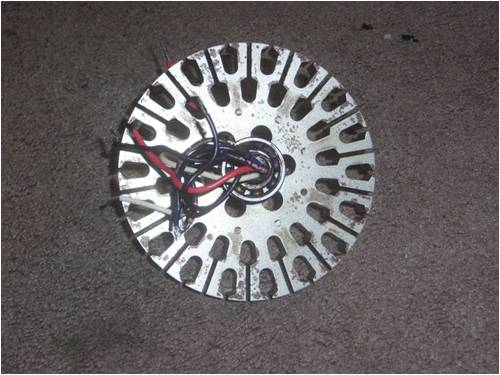
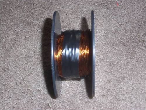
I found that the average amount of windings on the outer coils was 315 and the inner was 235. I also looked around town for some additional magnet wire that I can use with this, & I must say that around here it is slim pickins! I did find some #20 in a half pound spool and that was the only one of its kind. Everything else was like #30 wire or #24 in 50ft increments at super expensive prices. SO here is what I am thinking. I am going to mill out the leg to equal the inner diameter size which means an additional 2mm on each leg. Then I want to run this as a 3 phase stator so I will use 3 coiled on the outer diameter and 3 on the inner diameter. I will probably winde my extra wire plus a single strand of the original wire. I have on order right now (12) 1" X 1/2" X 1/2" N42 magnets with 37lb of pull force and (12) 1" X 1/2" X 1/8" N42 magnets with 11lb of pull force. The inner diameter of the coiled is about 5/8" and when measured before disassembly about 1.5" tall. Does anyone think I am going the wrong direction? Am I making any terrible mistakes? All thoughts and criticism is welcomed! Will it work? Well lick your fingers and touch the two leeds. PZZZZZZZT |
||||
| Gizmo Admin Group Joined: 05/06/2004 Location: AustraliaPosts: 5078 |
Hi arpolis What size are your magnets? I did a ceiling fan conversion years ago, and learned a few tips. My stator was single phase, yours is two phase. My magnets were as wide as each stator pole, yours should be as wide as two poles. My magnets were 3mm thick, so I machined 3mm from the inside of the hub, and stuck the magnets in with superglue. When I put it together, it suffered extreme cogging, was very hard to spin from standstill, but once going it spun OK. Tip 1, you need to offset the magnets to reduce cogging. Dinges wrote a very good article about the different ways to reduce cogging, you can see it here. Look for the Offset method. http://www.otherpower.com/images/scimages/3538/decogging_tut orial_V1.pdf After I rewound the coils, I discovered they were shorted to the stator laminations. The corners of the laminations are sharp, and will break through the wire enamel. A layer of insulation tape didn't help, even though I was careful. I ended up using some thin cardboard, like from a cereal packet, on all corners before I started winding. It was a mongrel of a job. My conversion did make good power, about 100 watts from memory, but the cogging was so severe I had to spin it by hand to get it started, even in a strong wind. Once going, it made a hell of a racket, very noisy, but it did make watts. Glenn The best time to plant a tree was twenty years ago, the second best time is right now. JAQ |
||||
| arpolis Newbie Joined: 04/08/2010 Location: United StatesPosts: 26 |
Hello gizmo Ty for the coging link. I will definately check that out. Now my mags are 1/2" wide because that is the inner width of each coil. You said I should be twice the width of each pole? You talkin total coil size, inner width, or the width of a single "leg" of metal? In that same order twice if either would be 60mm, 24mm, or 40mm. From what little I know I figured a 3/4 coil/mag ratio with the mags the same width as the inner width of the coil was good. Would that be wrong for this application? Will it work? Well lick your fingers and touch the two leeds. PZZZZZZZT |
||||
MacGyver Guru Joined: 12/05/2009 Location: United StatesPosts: 1329 |
arpolis From memory, I think these ceiling fan motors are wound in series, meaning the outside coils are all one wire as well as the inside ones, all another wire. If that was the case when you unwound things, if it were I, I'd wind ONE test coil and spin the thing to see what voltage is produced from just ONE coil and wind accordingly. If it is your intention to make this 2-phase, you may be surprised at how much electricity just one coil makes. I don't think you want a high-voltage, low-amperage machine, but I could be wrong there. At any rate, wind one coil and see what it makes, then multiply that result by the number of coils you intend installing and you can get an idea of the output. Remember too that there are "multipliers" involved, meaning that with "star" connection, there is either a 1.4 or a 1.7 multiplier that comes into play (for 3-phase at least) as well as a 1.4 or a 1.7 multiplier that comes into play for it being a.c. I don't remember which is which, but suffice to say one goes for one and the other for the other. In my little ax-fx build, all I need is 1.8v per coil (9 coils) to reach an ultimate output of something like 13.8 volts (again from memory). Hope this isn't as confusing as I'm thinking it might be, but there are lots of variables building an alternator. If you were to arrange your magnets so that a N passed over the first coil, while a S passed the 2nd and another N were over the 3rd and so on AND you were to wind the consecutive coils alternately say clockwise, then the next one counter-clockwise and all were in series, then each revolution, you would get the voltage of one coil times however many coils are in your array. This adds up fast. I'm building a little iron-cored unit and if my calculations are correct (big if!) I should be able to achieve 14 volts on only 6 coils with a mere 36 winds per coil. Haven't actually tried it yet, but if that's the case, you can bet I'll make the wire size ginormous to lower the coil resistance and garner more current! To clarify that a bit, as magnetic flux travels across windings in a given direction, the current induced travels one way for wires on one side of the coil and the other way for wires on the other side of the same coil. This is what we refer to as "canceling". It's a problem that can be turned into a solution, if you wind things properly. The idea is to have N pass a coil one way while a S passes the same number of turns turned the opposite direction. Doing this creates 2 pulses, each traveling in the same direction down the wire and adding instead of canceling. By alternately using coils wound one way, then the opposite way, then back to the original direction, we can use this phenomena to our advantage. Instead of canceling, the action doubles the output. Make sense? . . . . . . Mac Nothing difficult is ever easy! Perhaps better stated in the words of Morgan Freeman, "Where there is no struggle, there is no progress!" Copeville, Texas |
||||
| arpolis Newbie Joined: 04/08/2010 Location: United StatesPosts: 26 |
TY Mac! That does make a good bit of sense. I still have a few days befor I will see my magnets so I guess I will get on with modifying the casing a bit. I want to straiten it out and re-bend it to give me about another half an inch of room so I can make sure there is plenty of steel backing for my magnets. Oh and I just re-read your post gizmo and the shorting problem I think will be ok for me. This fan came with some nice springy plastic parts that fit into the winding holes to protect the wire. We shall see how that works. Will it work? Well lick your fingers and touch the two leeds. PZZZZZZZT |
||||
| arpolis Newbie Joined: 04/08/2010 Location: United StatesPosts: 26 |
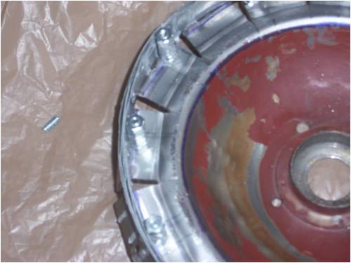
Welcome to this weeks update on the project. If I keep working on it today with no more interruptions I think I will be able to test my first coil set to see what I get voltage/amps wise. I have received my magnets and they are 12 (1" X .5" X .5") and another set of 12 (1" X .5" X 1/8"). I put my magnets in the case to see how the stator fit and found that I miss measured something. There is 0 room for any gap!  You can see the setup in the next two pics. You can see the setup in the next two pics.
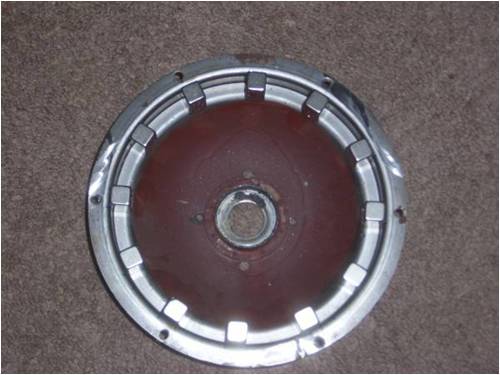
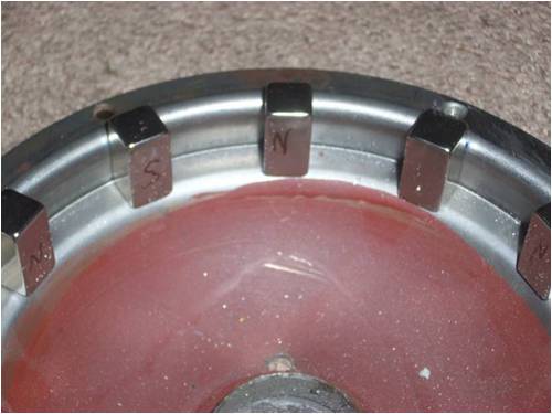
And to boot the lack of gap was without the 1/8" mags. SO I went on and instead of getting new magnets I wanted to modify the case a bit. I have it roughly shaped out and built with a steel ring for the magnets. I do understand that is curently has some balancing issues but that will be corrected later. Here is what I have done so far: 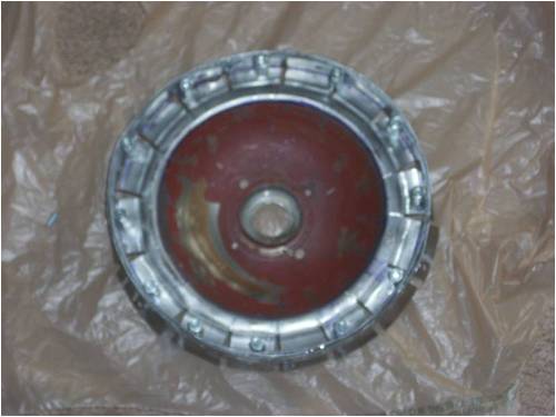
Again any questions and suggestions are always welcomed! Will it work? Well lick your fingers and touch the two leeds. PZZZZZZZT |
||||
| arpolis Newbie Joined: 04/08/2010 Location: United StatesPosts: 26 |
Here is this weeks update and bad news I would say. Bellow you will see my first rough draft of the ceiling fan and I got bad results. I added some steel strips to reduce the space between the magnets and the stator. I did find that the magnets where positioned a little low in relation to the copper coils so as a temporary measure I added two pennies under the magnets to bring them to an appropriate height. The 9 coils you see are all one piece of #20 magnet wire with 50 wraps in the outer coils and 35 in the inner coils. I clamped the stator down and spun the case around and got some pretty pitiful results. 2v at 400mA "Approximately", and that was as fast as I could spin it by hand. So I assume having the coils at different lengths from the magnets is probably not efficient at all but I thought it may only help and the more coils I could get in there I figured would increase the voltage. Do you all think if I removed the inner coils would the output be better? If I can get the #20 wire to work, I will use the original wire from the ceiling fan and can easily get 175+ turns with 3 of those lines in hand. I wanted to have 3 coils on the outside stator dedicated for that. At this point I am up for any suggestions and/or criticism. 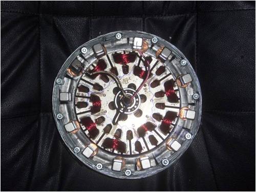
Will it work? Well lick your fingers and touch the two leeds. PZZZZZZZT |
||||
| arpolis Newbie Joined: 04/08/2010 Location: United StatesPosts: 26 |
OK here is what I have discovered so far. With the magnets at hand in the configuration I have I find the 20AWG wire is way to thick for any real application here. I wanted to use thicker wire in order to have better amps while still having an overall charging voltage for a 12V battery. 50 turns is as many as I can fit into the small coil spaces. I have tried 6 coils, 9 coils & T.S. every connection in that stator and can not get more than 2.7V at 400 mili Amp. My next step is to go back to the original wire and I will try 250 wraps with 2 in hand. We will see how that goes next. Will it work? Well lick your fingers and touch the two leeds. PZZZZZZZT |
||||
| Page 1 of 2 |
|||||