
|

|
Forum Index : Windmills : MPPT more efficient than Battery Charging
| Author | Message | ||||
| DaveP68 Senior Member Joined: 25/11/2014 Location: New ZealandPosts: 292 |
The aim of this topic to show how the efficiency of an F&P stator in different modes and over an RPM range translating to the most common wind conditions (3 – 8 m/s). This was to evaluate the difference between using MPPT (GTI) vs directly charging a Battery. There have been many comments on this forum re there not being much of a difference in the "accumulated power output" using MPPT (GTI) vs Battery Charging on an F&P wind turbine. For starters there is no point in data logging the difference between axial flux against a F&P Dual as that is not the same comparison having one set up MPPT (GTI) and the other Battery Charging. If that is a way to compare wind turbine set ups, that shows a lack of understanding of how each component interacts on different wind turbine configurations with MPPT or without. Here is my new test rig with a fully adjustable load (blue module below) that can simulate MPPT (GTI) or Battery Charging. Here is a graph of an F&P stator’s efficiency in 3 different modes, MPPT (GTI), Battery Charging and Battery charging using a Capacitor Doubler. 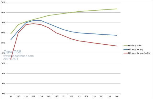 Have also taken into account the various losses such as efficiency off motor controller, friction, I^R copper loss etc. Here are 3 graphs of input power vs output power measured over similar RPM ranges. The motor controller used to drive stator # 1 as a motor is torque limited above 270 RPM so there is no data for above that RPM limit. It also closely represents the winds in a range of 3 – 8 m/s. My data logger was to take a video of each test from 92 up to 245 RPM and enter all the 4 readings displayed as they updated. Readings taken were RPM (white display module), AC power meter measuring input to motor controller, then Volts + Apms on stator #2 output at DC side of 3 phase rectifier. First is a graph of simulated MPPT (GTI) which results in the best overall efficiency up to 245 RPM. 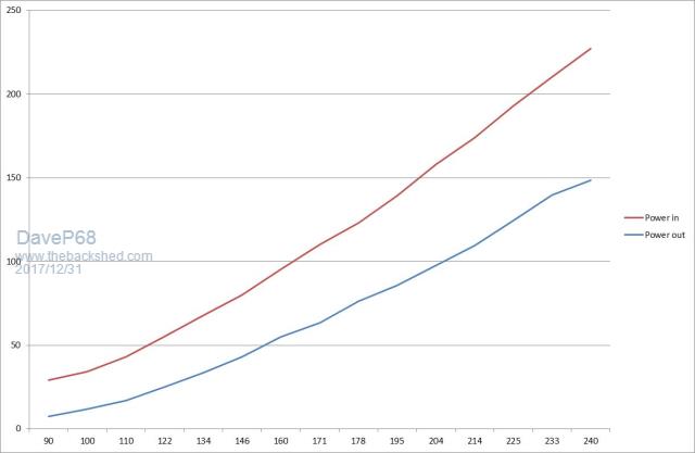 Second is a graph of simulated Batter Charging. 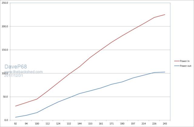 Third is a graph of simulated Battery Charging but this time using a capacitor doubler.  ** Please note in last 2 graphs, only half of a stator (1x 6c) was used on the output side. The motor torque required to drive a whole stator was almost double as the stator output current approached it's maximum limit due to stator voltage being clamped in battery charging mode. This allowed for a more equal comparison between the different set ups as the input drive torque requirement remained fairly constant over a similar RPM range for each test done. So the conclusion I've reached here is Battery Charging quickly becomes less efficient as the RPM increases just above the cut in. The MPPT (GTI) system is more complex to impediment, but is the most efficient way to extract power from an F&P stator or any PMA for that matter. Comparing 2 identical F&P dual wind turbines, one using MPPT (GTI) and the other Battery Charging, the accumulated output power difference over time would be >30 % better using MPPT (GTI). It's all about keeping the blades in the TSR sweet spot in order to gain the "optimum" amount of torque for a given wind speed. Power = Torque x RPM divided by 9.549297 with Power in Watts, Torque in Nm. This is how MPPT works, it keeps the TSR at a point as close as possible to the best Power Coefficient over a wide range of wind speeds. 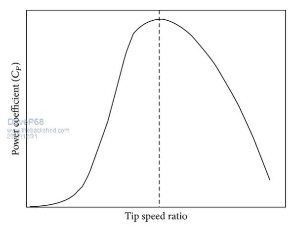 If too much torque is taken from the shaft then the TSR will drop off creating further losses. The blades will produce more torque at that lower RPM but but at the expense of a lower Power Coefficient, thus resulting in lower power transfer to the PMA. The PMA having less RPM to work with will produce less power output, a law of diminishing returns!! Here are graphs of the full stator tests when simulating Battery Charging including with a Capacitor Doubler. 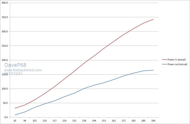 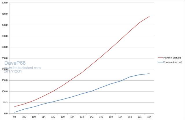 Note the much higher input power required at a much lower RPM for not much extra output power from the stator. When coupled to blades on a wind turbine these configurations will be on the downside of the optimum TSR operating range only making the accumulated power output even worse!! Hope this is of interest for those wanting to build an F&P wind turbine. There are realities if you do not accept, will lead to frustration because you will be spending time on wrong assumptions and the results cannot follow! The Dunning Kruger Effect :) |
||||
Madness Guru Joined: 08/10/2011 Location: AustraliaPosts: 2498 |
My understanding of this is that holding the voltage down to the battery bank volts means current has to rise a lot to get much power and as you have shown it is hamstrung. I have seen quite a bit of information from Midnite about this and the advantages of using an MPPT in conjunction with a wind generator. I was talking to Oztules about this not long ago, he suggested using a PWM regulator in conjunction with a GTI. By sensing the RPM of the generator and using this value to set the ideal PWM value to let the generator spin up to its sweet spot. This could be done without any modification to the F&P motors. There are only 10 types of people in the world: those who understand binary, and those who don't. |
||||
| DaveP68 Senior Member Joined: 25/11/2014 Location: New ZealandPosts: 292 |
Hi Madness The most important factor in matching wind turbine blades with any PMA (F&P stators in this case) is to keep the RPM generated by the blades in their TSR sweet spot. Not easy to accomplish, as the shaft RPM must remain linear with wind speed and the power that the PMA has to take must follow the wind power³ "cubed law". A graph of wind power vs RPM over a speed range of 2 - 12 m/s using 3 m blades. 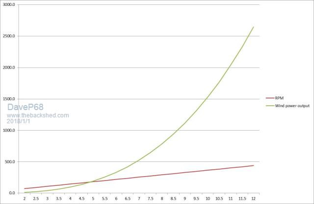 I've developed a complex algorithm which uses "Closed Loop Control" that can used to operate the PWM in an inverter used for battery charging or GTI modes. At this stage it's being used to control the PWM dynamic brake circuit in that blue module in the photo. That is how I can simulate MPPT to produce the graphs in the previous post with lots of data points. Without this MPPT it would have been more difficult to prove the most efficient mode of operation. I like the way Don Brown explained this very issue in the full article titled Wind Speed and windmills explained which is on this website. Here are the key extracts that relate to what I've outlined above. Conventional charging circuitry - A typical wind turbine alternator connects to a (bridge) rectifier, which then connects to the battery under charge. Note that current can only flow from the alternator to the turbine once its terminal voltage exceeds that of the battery voltage, plus the diode bridge forward voltage drop. The current waveform is therefore unlikely to be a clean sinusoid, and some harmonics will be generated. Conventional charging circuit shortcomings - As noted above, for the turbine to operate at maximum efficiency, it must run at or near its design TSR. This requires that its turbine speed must linearly follow the wind speed. For alternators with fixed excitation (All PMA's), the no-load voltage will be proportional to shaft speed. The problem is that, with conventional circuitry, the alternator is more or less locked to the battery voltage, and the turbine will generally be operating below optimum speed as a consequence. Switchmode charging circuit - The alternator is connected via a switchmode charging circuit, which can let the alternator operate at voltages significantly above the battery voltage. The switchmode circuit works by connecting the alternator DC output voltage to the battery for a brief period. The current that flows is limited by the inductor, which also stores energy in the form of a magnetic field. When the switch opens, the polarity of the voltage of the inductance reverses, and current flow is maintained through the battery and the Shottky diode while the magnetic field dissipates. The current burst flowing into the battery is thus longer than the current burst from the alternator side, while the voltage is lower. As very little energy is lost in this process, over a burst cycle, power in effectively equals power out, and the system works as a DC transformer. This permits the alternator to operate at a higher voltage consistent with a higher turbine speed. Closed Loop Control - If the alternator speed and the undisturbed wind speed are known, then the controller can be set to maintain a constant ratio between the two. If the wind should increase, the controller would shift to a higher reference voltage consistent with the expected higher turbine speed, thus unloading the turbine and assisting it to accelerate to its expected speed. If the wind speed drops, the voltage reference would lower, loading up the turbine and recovering energy from it while it slows to its new, more appropriate speed. How much better? - As the wind is always changing, it is difficult to measure the extent of any improvements that you think that you have made unless you have access to a wind tunnel. The solution is to have two units identical in every respect except for the feature that you are testing. By mounting them on a common pivoting support and exposing them to an airflow that is as undisturbed as possible, they should see more or less the same air-flow. By measuring the amp-hours output from each into a common load, the benefit of any enhancement can soon be checked. Using the amp-hours check with no enhancements fitted will also establish whether there is any difference before you start testing. David There are realities if you do not accept, will lead to frustration because you will be spending time on wrong assumptions and the results cannot follow! The Dunning Kruger Effect :) |
||||
SparWeb Senior Member Joined: 17/04/2008 Location: CanadaPosts: 196 |
Whew! That's a lot of work, Dave. [quote=DaveP68]Have also taken into account the various losses such as efficiency of motor controller, friction, I^R copper loss etc.[/quote] Has this given you a torque curve for the F&P drive motor? Do you have a copy of the manufacturer's? Steven T. Fahey |
||||
| DaveP68 Senior Member Joined: 25/11/2014 Location: New ZealandPosts: 292 |
Hi Steven Very good question as I hadn't bothered graphing that data even though I was able to closely calculate what it is. I don't have any manufacturing data from Fisher & Paykel but was able to work out most of input modes to the motor by watch the PWM wave forms etc. Also run up the motor on its own over same RPM range logged input power data vs RPM. Then connected the test stator acting as the alternator with no load on it and ran same test. That way was able to calculate closer to what is going on in the complete drive system. Here are 3 graphs of Torque in Nm over the test RPM ranges as seen in this topic. First is for simulated MPPT. 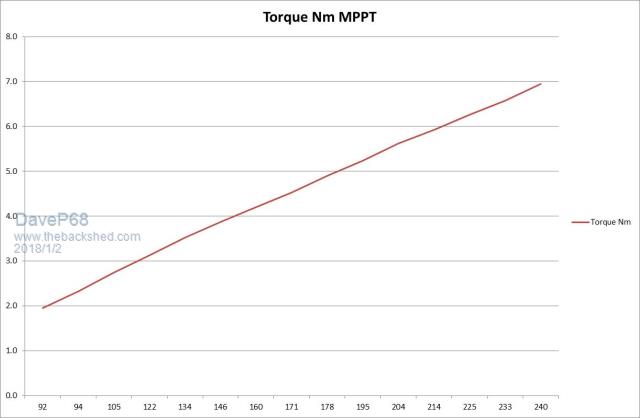 Second is for simulated Battery Charging. 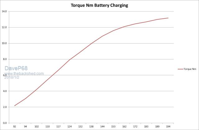 Third is for simulated Battery Charging via a Capacitor Doubler. 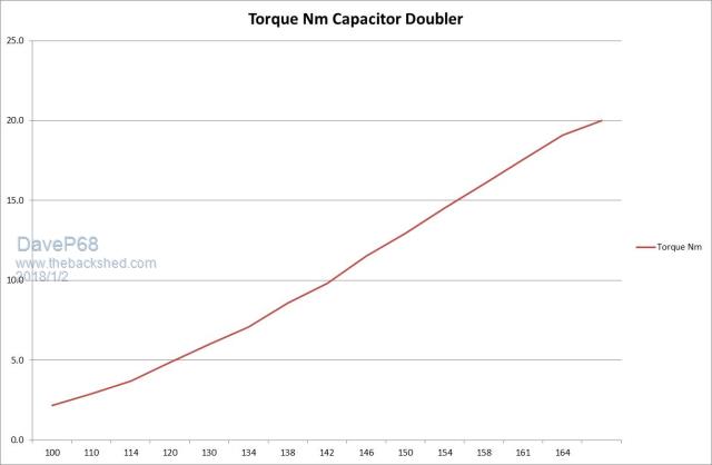 Note how the Torque curve for a stator feeding into Capacitor Doubler is similar to the curve in the MPPT graph. If one thinks that Capacitor Doublers can replace an electronic MPPT system my new data says that is definitely not the case. Look up the "Dunning Kruger effect" to check out why I'm saying it this way. Capacitor Doublers perform even more poorly than directly charging batters on F&P stators from my new data. To achieve better power transfer efficiency in the 3 - 8 m/s wind speed range, just rewire the stator to suit the best TSR. The older 42 pole stators are not as suitable for this with a more limited rewiring combinations compared to the 36 pole copper stator with black rotor caps. Also 36 pole stator are factory decogged! I can now see why there was lots of effort 9-10 years ago put into capacitor doublers on F&P stators, as the 36 pole copper stators were not common back then. This is not a criticism to all those who did probably hundreds of hours testing and have also ended up using them on F&P Wind Turbines. Capacitor doublers do work ok with MPPT systems with a smaller loss. With 36 pole copper stator more common, they can be wired into more combinations to match the stator to the battery voltage for charging while staying close to the best TSR. But there will be much higher losses than a Electronic MPPT system. One advantage relating to capacitor doublers that is that tends to keep the blades under control in high winds by taking lots more torque at high RPM as per my graph above. A stator directly connected to a battery will tend to go into iron core saturation and has the potential to result in blade run away if the furling system doesn't do it's job properly at this point. So it's not all doom and gloom for capacitor doublers used with F&P stators. I've now put hundreds of hours for no financial return to date into F&P stator (my day job repairing F&P smart drive washing machines pays very well). On a related note to all this, I'm now working on a simple electronic MPPT circuit using PWM to more efficiently charge batteries for those who are interested. It will end up being published in more detail under electronic projects. A photo of my latest purchase towards this new project, a Tektronics MSO 2024. Won't say how much this secondhand unit cost me, was <10% of the current model. There are realities if you do not accept, will lead to frustration because you will be spending time on wrong assumptions and the results cannot follow! The Dunning Kruger Effect :) |
||||
| kitestrings Senior Member Joined: 23/04/2014 Location: United StatesPosts: 102 |
Hi D, Happy New Year, and glad to see you your back (here & OP). I read quickly thru some newer posts to me on OP, and then here. Cool stuff. I've a number of questions, but may need to absorb it a bit more. A couple things - I was reminded of a post some years ago by Flux on "Load Matching", and that thought just occurred to me, when I came on this reminder from SparW. My advance apologies to the Mod's, but I think it is on topic, and there may be some value to you if you hadn't seen this before: http://www.fieldlines.com/index.php/topic,149396.0.html Regarding fillm's comments, I questioned that one too. Looking at it a second time however, I think his point was different, which is that much of the gains of the GTI are found at higher rpms. And, all things otherwise equal, looking at accumulated energy may be closer (presumably due to more run-hours at lower wind speeds). His data logging reference, I believe, was suggesting a comparison of the one variable, in similar fashion perhaps to the side-by-side we saw with -without GOE222 blades. I could be wrong. A few questions: What are the purported benefits of the Battery Cap Dblr? The efficiencies are surprisingly lower in your chart. Why is MPPT only pared with GTI? To me it is the most compelling new (in the last ~4 years) development for battery charging applications. ~ks |
||||
Madness Guru Joined: 08/10/2011 Location: AustraliaPosts: 2498 |
Dave is there any more of those CRO's where that one came from? There are only 10 types of people in the world: those who understand binary, and those who don't. |
||||
| DaveP68 Senior Member Joined: 25/11/2014 Location: New ZealandPosts: 292 |
Hi ks Happy New year to you and the family at your end. Had a good read through OP topic you jsu made reference to, a big read bit very informative. I't is a bit lite on the efficiency aspect though which I've covered off in far more detail in this topic. The big bit seems to be over looked on this topic is energy transfer efficiency. MPPT which ever way it is used is the best system to make the most efficient use of energy generated by the Wind Turbine blades on the shaft. Don't get confused by fillm's comments re GTI being the only form of MPPT available. A type of Buck down converter with a wide input voltage range with a fixed voltage output for battery charging are available on the market for a price. From what I understand fillm has never set up 2x F&P Dual wind turbines both using same GOE222 blade size side-by-side. First one using some form of MPPT and the other direct charging batteries with or without a capacitor doubler. Only then after lots of detailed data logging will the results show what's just proven to be the case with my custom built F&P dynamometer. I don't need a wind turbine to prove my point here as PMA set up in my view is just as critical as all the hard work that goes into mounting blades, balancing them etc etc. That is a bold statement to make, but my point here is a MPPT system set up correctly does most of the hard work for you. Just connect up the 3 phases from a suitable PMA and stand back and watch it pumping out the power day after day just more efficiently. One other consideration with charging batteries is they are not 100 % efficient in the charge discharge cycle. Lithium-ion can be as high as 95 % but Lead Acid is 80 % efficient at best. Here are 3 the same graphs showing the input torque of 3 different F&P stator set ups, but this time with "Scaled" Volts & Amps. Results speak for themselves!! First simulated MPPT. 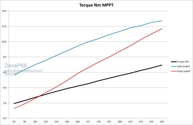 Second simulated Battery Charging.  Third simulated Battery Charging via a Capacitor Doubler.  Note how the current from the stator runs in proportion to the Torque in the second and third graphs!! So we can now say with MPPT the equation of 2+2=4, but with battery charging or even worse a capacitor doubler 1 being voltage + 2 being current does not = 4... Hope this clarifies your questions ks and also allows others following this topic to gain a deeper understanding of how to make better use of F&P stators on wind turbines. Form how I see it, this will apply to ALL PMA's no exception! Permanent magnets can't be fooled  There are realities if you do not accept, will lead to frustration because you will be spending time on wrong assumptions and the results cannot follow! The Dunning Kruger Effect :) |
||||
| DaveP68 Senior Member Joined: 25/11/2014 Location: New ZealandPosts: 292 |
Sorry to say Madness it was a one off sale, very pleased with it as bandwidth is up to 200 MHz at 1 G/s. It's also in very good condition. There are realities if you do not accept, will lead to frustration because you will be spending time on wrong assumptions and the results cannot follow! The Dunning Kruger Effect :) |
||||
| DaveP68 Senior Member Joined: 25/11/2014 Location: New ZealandPosts: 292 |
Found an error in the Capacitor doubler used to provided the test results above. Was using too high capacitor value in the test unit. This was due it being used in the past for testing of a 2 to 1 input voltage range MPPT GTI inverter which doesn't behave like a battery at all... The capacitor value was 280 uF AC way too high! Changed them over to 120 uF AC, but found they were still a little too high. Still gave good results though so left them in for the test anyway. The capacitors actually need to be about 80 - 100 uF AC to get the best results. Used a 80s stator wired Delta into a simulated battery set at 57 VDC. It ended up working well compared to my MPPT system and a lot better than what can be seen above. My guess is the best efficiency of a capacitor double will be 70 to 72 % at best in it's sweet spot for where most power is produced. Capacitor Doublers efficiency is around 15 % less than a good MPPT system, so you can't get something for nothing!! Here are my updated graphs showing the change in power input vs power output and efficiency compared to MPPT.  Note in colour "Green" I've included the equivalent "wind shaft power" that would be driving a 0.8 mm stator on an actual wind turbine. 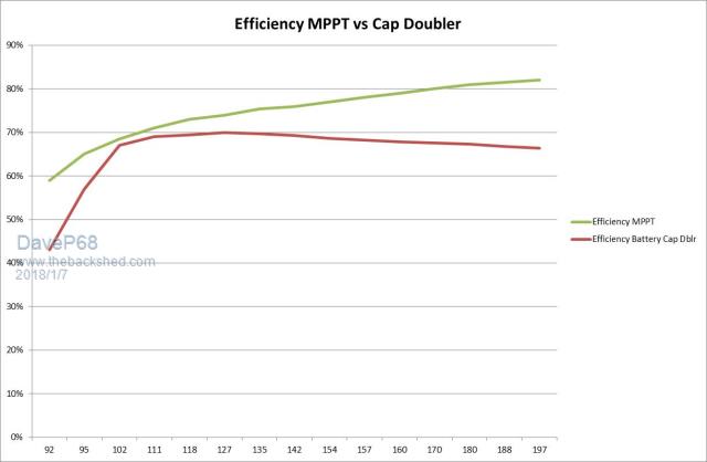 Hope this is of interest to those following this topic. Can now calculate all the capacitor values for Capacitor Doublers for any F&P stator wiring configuration, for both star and delta that will be used with a 24 or 48 VDC battery system. This includes all different versions of F&P stators 42 pole 100s, 80s, 60s and 36 pole copper with black rotor caps. Have the confidence to do this now, as able test any configuration on my VFD test rig and plot the results up to 250 RPM with a high level accuracy. PS top graph has been edited with the equivalent "wind shaft power" included. There are realities if you do not accept, will lead to frustration because you will be spending time on wrong assumptions and the results cannot follow! The Dunning Kruger Effect :) |
||||