|

|
Forum Index : Windmills : F&P Stator Wire diameter
| Author | Message | ||||
| DaveP68 Senior Member Joined: 25/11/2014 Location: New ZealandPosts: 292 |
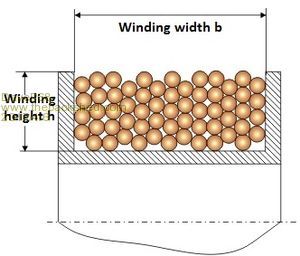
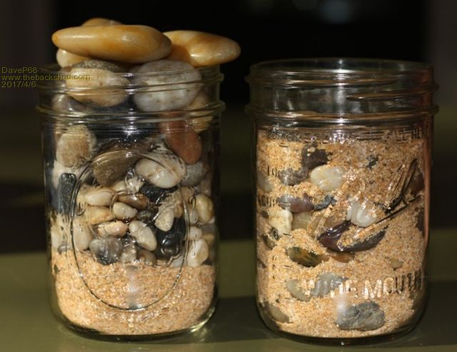
There seems to be a bit of a misunderstanding of how wire diameter affects the power output and/or efficiency of F&P stators. Yes thicker the wire the higher the current output but lower the voltage output of the stator. So the 100s has the larger wire diameter of 1 mm. In fact the most efficient stators, that also put out more power are the 60s 42 or 36 pole copper stators. The main reason for this is how much the total volume of copper that can be wound on each pole. Please refer to the pictures below.  Notice the air gaps between the wires of this coil cross section.  Now your probably thinking I'm nuts showing you 2 jars in the lower picture with small rocks, stones and sand. What these illustrate is that as the wire diameter is made lager the air gap between wires grows at a disproportionate rate. So if we fill a jar with just sand most of the space is taken up. Hence 60s stators have 0.6 mm wire diameter so are closer together with less air gaps. So from the measurements I've made on the same rotor cap (magnetic field constant) when correctly load matched the 100s puts out 5% less power than a 60s re wired in such a way that the voltages and currents are similar. Example 100s star is 2.6 ohms from phase to phase. A 60s 42 pole re wired 2x 7p Delta is 2.667 ohms from phase to phase. That's about 2.5 % difference so voltage and currents will be close enough for comparison. When the 2 different stators power outputs are measured at the same RPM the 100s is about 5% less. So it shows that lager wire diameter does not translate into higher output power. Also the cogging on the 100s is more when compared to the other stators. Yes they can be decogged but not as well as The 36 pole comes factory decogged. This which makes a difference in low wind performance. After all Fisher & Paykel went to the smaller wire diameter for motor drive efficiency, so that fact works both ways if you want to make power from them! Hope this information is of some use to anyone that visits this post. There are realities if you do not accept, will lead to frustration because you will be spending time on wrong assumptions and the results cannot follow! The Dunning Kruger Effect :) |
||||
| Warpspeed Guru Joined: 09/08/2007 Location: AustraliaPosts: 4406 |
This is all very true. A larger number of turns of fine wire can certainly pack significantly more copper into a given fixed winding volume. The main difficulty with that is your extra power then comes out at a higher voltage with reduced current capability. That problem can easily be overcome by winding on multiple strands together, so there can effectively be two or three windings of identical turns count, connected in parallel. Cheers, Tony. |
||||
| joebog1 Senior Member Joined: 07/11/2015 Location: AustraliaPosts: 114 |
As warpspeed says using bifilar wire ( two small strands together) or trifilar winding ( three small wires) etc etc. Slightly more expensive but reducing "waste winding space" square ( or almost square) wire is available, but its trickier to wind, because of the control needed to keep the wire bending off course. If you are really loaded you can buy hexagonal wire that has no waste space at all. All are available in quite a number of guages on "that" website. Joe |
||||
| DaveP68 Senior Member Joined: 25/11/2014 Location: New ZealandPosts: 292 |
Hi Warpspeed & joebog1 Both your points are very valid. The 100s (1 mm wire) F&P stator can deliver the most current for all the 42 pole stators. Even when the other 80s & 60s are rewired to emulate a similar impedance they may put a bit more voltage out but less current. I'm interested in rewiring a 36 pole stator with 0.8 mm or 0.9 just to check what maximum current they can deliver. Now shifting my view point on these stators used to directly charge batteries. With capacitor doublers requiring more current to drive them, have now been able to get a projected >1 kW from a Dual 42 pole set up. This was due to me understanding the maximum current flow better over RPM range. There are realities if you do not accept, will lead to frustration because you will be spending time on wrong assumptions and the results cannot follow! The Dunning Kruger Effect :) |
||||
| DaveP68 Senior Member Joined: 25/11/2014 Location: New ZealandPosts: 292 |
Using power factor correction capacitors on a 12x 1p 36 pole delta with black rotor cap, can output 1.5 kW at only 600 RPM. Voltage was 57.1 VDC at 26.3 Amps. Just goes to show that a stator with only 0.6 mm (60s) wire diameter, can way out perform a any 42 pole stator 80s or 100s. My prediction is that a 12x 1p 36 pole delta stator can output 2000 W at around 700 RPM set up correctly. There are realities if you do not accept, will lead to frustration because you will be spending time on wrong assumptions and the results cannot follow! The Dunning Kruger Effect :) |
||||
| kitestrings Senior Member Joined: 23/04/2014 Location: United StatesPosts: 102 |
What does the 60, 80, 100 represent? Is it a series, or somehow tie to size? Your photo caught my eye. I had a high school physics teacher that approached the podium at graduation with two similar jars. A slightly different take, but his point was that if you spent all your time on the little things that fill our days, you don't have room for the important (larger) things in life. He's, to this day, still one of my favorite teachers. Thanks for the visual. ~ks |
||||
| DaveP68 Senior Member Joined: 25/11/2014 Location: New ZealandPosts: 292 |
Hi ks Thanks for shearing your informative story and such words of wisdom.  Yes the 60, 80, 100 represent the wire diameter of each Fisher & Paykel stator. With 6O 0.6 mm is 60s, 0.8 mm is 80s and 1 mm being 100s. That's why I stated above the most efficient stators, that put out the most power are the 60s 42 or 36 pole copper stators. It comes down to the air gap between each wire in the coils. Smaller the air gap the greater the energy density. The focus in the past has been to max out the current from these stators by using the larger wire diameter versions. The bit missed along the way is even the 60s wired correctly can put out the most power for a given RPM with a similar current. Example an 80s wired 14x 1p star will output 1670 W at 2000 RPMs to say fast charge batteries at 59 VDC 28.3 Amps. If 3 of the same type of 80s stators are used, then the output will be 5 kW. This configuration has no power factor correction. The same output power of 1670 W can be reached at "only 650 RPM" using power factor correction capacitors on a 36 pole wired 12x 1p delta with black rotor cap. With 3 stators one could get 6 kW output at around 700 RPM. Less is more!  David There are realities if you do not accept, will lead to frustration because you will be spending time on wrong assumptions and the results cannot follow! The Dunning Kruger Effect :) |
||||
| joebog1 Senior Member Joined: 07/11/2015 Location: AustraliaPosts: 114 |
I hate to keep harping on the same subject, but check this site: http://www.hi-wire.co.uk/acatalog/rectangular_wires.html As you can see, the actual "circular" mil size of square wire ( or hexagonal wire) is way larger for the same "diameter" . Ok square ( or hex) wire doesnt have a diameter as such, and has no airgaps ( perfect winding pitch assumed ) so maximum current and voltage can be obtained with good design. I have only fiddled with F&P stators but was very unimpressed with build quality ( I wasnt going to rewind a stator) and didnt follow it on. ( more fool me it seems). I dont have the funds to buy more wire ( I already have a ton or so, ALL round and varnish not poly u solder through ) BUT, with some thought and some money I am sure the F&P stators could be made into something nice. I have only been half watching the thread, but a question that does arise ( in my stupid head anyway) what is the maximum flux density that the iron can handle ? What sort of iron is it? You can keep adding/improving/modifying but at some stage that iron is gonna be so full of flux lines it will saturate and next to no increase will be apparent, apart from the heat. This will be most apparent at low revs of course, because as the speed increases so does the frequency, and so does the efficiency. er hmm sorry if I sound negative. Joe |
||||
| DaveP68 Senior Member Joined: 25/11/2014 Location: New ZealandPosts: 292 |
Hi Joe Have no interest in rewinding an F&P stator with a different types of round/hexagonal/square etc. I get my stators for free and only interested in pushing the limits of what they can put out at a reasonable RPM range of say 400 - 600 for use on Wind Turbines. Check out what oztules posted on my topic of 1.5 kW @ 600 RPM with PF correction Using these power factor correction capacitors it makes the voltage over double (under load) and the optimum current drops slightly as it goes into a form of resonance. I don't think there is much in the way of any extra heating occurring in the iron cores from what I can work out. David There are realities if you do not accept, will lead to frustration because you will be spending time on wrong assumptions and the results cannot follow! The Dunning Kruger Effect :) |
||||
| joebog1 Senior Member Joined: 07/11/2015 Location: AustraliaPosts: 114 |
Thx Dave  Joe |
||||