| Author |
Message |
Rubes
Newbie

Joined: 01/05/2009
Location: Posts: 36 |
| Posted: 04:38pm 21 Dec 2016 |
 Copy link to clipboard Copy link to clipboard |
 Print this post |
|
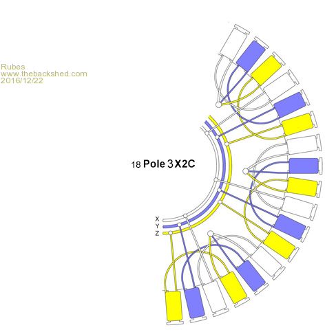
Hi Guys, just completed a micro Hydro project and because of limited head (17 metres dynamic) I have had to play around with the stator and have found an 18Pole3X2C

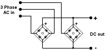
seems to give me optimal performance via bridge recifier as here  of 95v open circuit or around 100 watts 45 v connected to a 20 Ohm dummy load. Question is, is this stator putting out acceptable 3 phase ac or is this not the correct way to reduce the core, I have tried other full stator wirings (42pole7X2c and 42Pole2X7C)these give me far to high a Voc (over 200v)at the rpm. Intend to use a 150v MPPT controller for battery management and no dump load as the no load rpm is acceptable. of 95v open circuit or around 100 watts 45 v connected to a 20 Ohm dummy load. Question is, is this stator putting out acceptable 3 phase ac or is this not the correct way to reduce the core, I have tried other full stator wirings (42pole7X2c and 42Pole2X7C)these give me far to high a Voc (over 200v)at the rpm. Intend to use a 150v MPPT controller for battery management and no dump load as the no load rpm is acceptable. |
| |
flc1
Senior Member

Joined: 20/11/2011
Location: New ZealandPosts: 242 |
| Posted: 05:08pm 21 Dec 2016 |
 Copy link to clipboard Copy link to clipboard |
 Print this post |
|
Hi rubes, why not use the whole stator in 14x1c, or try a 36pole stator for some diffrent combinations, and or fit a tap in line above your hydro for rpm control? how many watts output are you after? how many batteries and what size ?Fred |
| |
Rubes
Newbie

Joined: 01/05/2009
Location: Posts: 36 |
| Posted: 05:59pm 21 Dec 2016 |
 Copy link to clipboard Copy link to clipboard |
 Print this post |
|
Hi flc1, 100 watt output would be a great addition in winter to feed a solar charged 300ah battery bank for the offgrid shack, still waiting for my controller but a brief test of full stator wirings direct connected to the bank causes significant rpm and power loss because of the high load and limited power input to hydro plant, the limiting factor being price of MPPT controllers that can handle the high Voc of full stators. No doubt there would be other wiring methods or rotor height adjustments that could be done as well but I need to know if my current stator wiring is acceptable. |
| |
flc1
Senior Member

Joined: 20/11/2011
Location: New ZealandPosts: 242 |
| Posted: 07:04pm 21 Dec 2016 |
 Copy link to clipboard Copy link to clipboard |
 Print this post |
|
Rubes, I would wait untill you get your mppt controller,and then start again with a full stator,cut to say 7x2?? and let the mppt do its work,with meters to see whats happening, trail n error I guess?your stator wireing looks ok, Fred |
| |
Rubes
Newbie

Joined: 01/05/2009
Location: Posts: 36 |
| Posted: 05:13am 22 Mar 2018 |
 Copy link to clipboard Copy link to clipboard |
 Print this post |
|
I have been running the microhydro setup as above for over a year now (as needed) through a 150v 35A victron mppt controller and notice the voltage input to the controller (after rectifier) varies from second to second by as much as 6v, so depending on the battery state of charge the voltage into contoller goes from say 48 to 54v as read by controller and rms meter. Just wondering if this is ripple from 3 phase output and if so would a smoothing capacitor help and given that I have no idea what the frequency is what cap should I pull out of the parts bin to try. |
| |
Madness

Guru

Joined: 08/10/2011
Location: AustraliaPosts: 2498 |
| Posted: 07:00am 22 Mar 2018 |
 Copy link to clipboard Copy link to clipboard |
 Print this post |
|
Might be worth talking to Victron about that, maybe it is how the MPPT works.
There are only 10 types of people in the world: those who understand binary, and those who don't. |
| |
DaveP68

Senior Member

Joined: 25/11/2014
Location: New ZealandPosts: 292 |
| Posted: 08:51pm 24 Mar 2018 |
 Copy link to clipboard Copy link to clipboard |
 Print this post |
|
Hi Rudes
What is the DC current reading at the output of the 3 Phase recifier?
I'm assuming you're using a 60s 42 pole stator? Can't see any reference to the type of stator and that matters a lot.
Also do you have any idea of what the RPM is of your reduced stator under load?
David
There are realities if you do not accept, will lead to frustration because you will be spending time on wrong assumptions and the results cannot follow! The Dunning Kruger Effect :) |
| |
Rubes
Newbie

Joined: 01/05/2009
Location: Posts: 36 |
| Posted: 11:03pm 24 Mar 2018 |
 Copy link to clipboard Copy link to clipboard |
 Print this post |
|
Hi Dave
Not at the shack now but from memory the open circuit dc current was around 8amps, mmm maybe not, been a while since I did the measurments I do know that the max output of controller into batteries is 8amp and yes it is a 42 pole stator not sure if it is 60s . No idea what the rpm is, it changes a lot depending on what the charge controller is doing at the time ie bulk or absorb/float. Just a thought, would the dc ripple frequency be 3hz per revolution given that I have 3X2C wiring ie 3 peaks per revolution, that would enable me to calculate the rpm? I will not be back at the shack for a few weeks so cannot test.After doing some reading of ripple control it seems a little above my pay grade and the system is working well as is but... mmm if it aint broke...
Anyhow thanks for any feedback. |
| |
DaveP68

Senior Member

Joined: 25/11/2014
Location: New ZealandPosts: 292 |
| Posted: 05:11am 25 Mar 2018 |
 Copy link to clipboard Copy link to clipboard |
 Print this post |
|
The frequency is determined by the number of magnet pairs in the rotor cap. Will be 28 Hz if rotating once per second (60 RPM).
Your stator could be a 80s if you're now stating 8 amps. In your first post you only made reference to 2.22 Amps which I calculated from the 100 W into a 20 ohms dummy load. That's what I used to make a guess of the stator being a 60s.
If your Multimeter has a frequency mode you can use that to work out the actual RPM of the stator.
There are realities if you do not accept, will lead to frustration because you will be spending time on wrong assumptions and the results cannot follow! The Dunning Kruger Effect :) |
| |
Rubes
Newbie

Joined: 01/05/2009
Location: Posts: 36 |
| Posted: 06:31am 25 Mar 2018 |
 Copy link to clipboard Copy link to clipboard |
 Print this post |
|
Sorry you are right the 8amps are on the battery side of controller which is at 12 to 14.4v so going in would be 2.2Amps 45v so presumably a 60s?.
Brilliant my multimeter has frequency mode so will work out rpm at full load, should be interesting.
Thanks |
| |

