|

|
Forum Index : Windmills : DIY 3 Phase Shunt Regulator
| Author | Message | ||||
| plasmahunt3r Newbie Joined: 10/01/2016 Location: United StatesPosts: 10 |
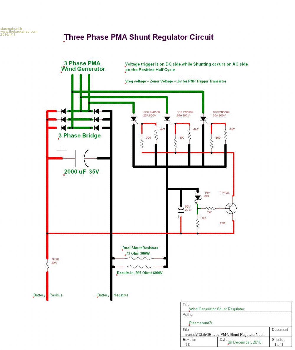
I have built and tested a 3 phase Shunt Regulator for my 12v Wind Turbine. I wanted to get this circuit out there for others who like to build their own. This circuit can be modified for 24v and 48V Turbines by changing the Zener and appropriate capacitor values. The circuit works by first converting AC into DC via the 3 Phase Full Wave Bridge Rectifier to charge your batteries. When the voltage limit is reached (set by Zener plus .6v for PNP Transistor), the SCR's are turned on and dumps the excess voltage to ground, via the dual 300W Dump Resistors. The dump occurs for each of the 3 AC phases on the positive half cycle and resets for each wave (SCR's turn off at zero voltage or negative voltage). Each positive AC phase dumps to DC ground. The Dump Resistors (dual parallel 300w = 600W) provides a load for the turbine so it is not a dead short. This dump is only for the Turbine and not a drain on the battery. This load also slows down the Turbine (Braking). [IMG]uploads/plasmahunt3r/2016-01-11_002837_3Phase-PMA-Shunt-Regulator4.jpg[/IMG] |
||||
| plasmahunt3r Newbie Joined: 10/01/2016 Location: United StatesPosts: 10 |
MY jpeg must not have worked. Here is the Circuit in GIF format: 
|
||||
| Gizmo Admin Group Joined: 05/06/2004 Location: AustraliaPosts: 5078 |
Clever and simple circuit, thanks. The best time to plant a tree was twenty years ago, the second best time is right now. JAQ |
||||
| Pete Locke Senior Member Joined: 26/06/2013 Location: New ZealandPosts: 181 |
Very clever  Another circuit for the collection. Well done and thanks. Only thing I will look at is the 0volt ref taken from the hot side of the shunt resistor. But if you've built it and it works, then there's probably no reason to do so. It's just me Another circuit for the collection. Well done and thanks. Only thing I will look at is the 0volt ref taken from the hot side of the shunt resistor. But if you've built it and it works, then there's probably no reason to do so. It's just me  |
||||
Downwind Guru Joined: 09/09/2009 Location: AustraliaPosts: 2333 |
Have I just had too many beers or just missing something here, I would have thought the zener diode should be before the base input of the transistor, as one would expect the transistor would remain latched and the base pin just voltage regulated to 14v by the zener. Humm? just cant work out how the transistor actually controls the switching of the SCR with the present circuit schematic. Pete. Sometimes it just works |
||||
| plasmahunt3r Newbie Joined: 10/01/2016 Location: United StatesPosts: 10 |
Downwind. This is a PNP Transistor. You would be right in Zener placement for a NPN. What happens, is when the Zener breakdown voltage is reached, The PNP gets a negative pulse on the base to turn it on. That allows the positive rail voltage to pass from the PNP emitter to the collector, which turns on the SCR's. I am using a PNP because I need positive voltage to the SCR gates to turn them on. You also might be confused because the PNP is drawn upside down from a comparable drawing. It was easier to draw my circuit with the PNP symbol upside down. Also, this drawing matched the placement of all my conpoinents on the actual PCB. The key is the emitter arrow in the PNP Transistor symbol. Here is a pic of the board layout. The PCB is made using the Island Cutter method. I use diamond hole saws to cut islands on the PCB to isolate components. The rest of the PCB is a negative ground plane. |
||||
| Pete Locke Senior Member Joined: 26/06/2013 Location: New ZealandPosts: 181 |
Correct. Until the Zener conducts (all looks backwards with PNP's) the emitter/base are tied in an off condition with the two resistors. With the 0v rail taken from the hot side of the dump resistors, you get a Schmitt trigger effect which will stop the regulator from fast switching. Very clever  |
||||
Downwind Guru Joined: 09/09/2009 Location: AustraliaPosts: 2333 |
Like I said too many beers and I missed the obvious, it all makes sense now. Pete. Sometimes it just works |
||||
| plasmahunt3r Newbie Joined: 10/01/2016 Location: United StatesPosts: 10 |
I have an update to this circuit. The voltage limit is set by Zener plus .6v for PNP Transistor. I have been using a 14V Zener (which was actually 13.8v plus the .6V for the PNP transistor resulting in 14.4V charging current. Since these batteries may be left unattended for a long period, I should use Float Voltage. For AGM battries, this should be between 13.5V to 13.8V (13.6V is optimum float voltage for AGM Batteries). The 14.4V may overcharge the batteries in the long term. For this reason, I am swapping out the 14V zener for a 13V zener. |
||||