
|

|
Forum Index : Windmills : active pitch control
| Author | Message | ||||
| brucedownunder2 Guru Joined: 14/09/2005 Location: AustraliaPosts: 1548 |
Just watch a short description on pitch control https://www.youtube.com/watch?v=fI5-DxQx7x8&feature=youtu.be I think the likes of Phill could do this ? Seems to me it's getting a lot closer to us "windys" now that these "DRONES" are becoming everyday flying machines.. I bet there are working designs out there for us DIY'ers . I'm very interested and will certainly "Hav a GO " Anyone want to chime in? Bruce Bushboy |
||||
| electrondady1 Senior Member Joined: 12/02/2009 Location: CanadaPosts: 208 |
midwoud has been quite generous this information on otherpower |
||||
| Midwoud1 Newbie Joined: 25/12/2012 Location: NetherlandsPosts: 23 |
https://www.youtube.com/watch?v=MRVGYVrgsdc Bruce. I have a succesful pitch contolled windgenerator design. Working good 3 years. 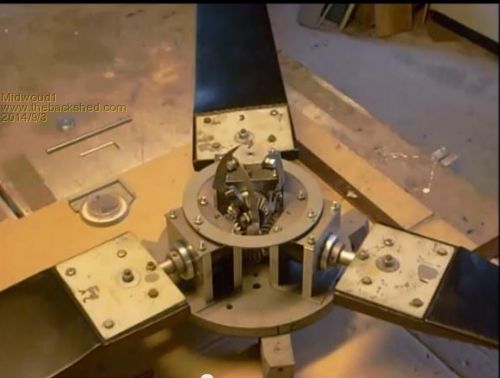
https://www.youtube.com/watch?v=9jaz3soqXLo 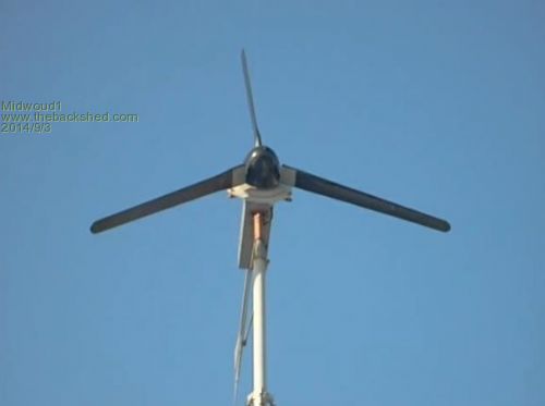
Rgds. Midwoud1 . |
||||
| brucedownunder2 Guru Joined: 14/09/2005 Location: AustraliaPosts: 1548 |
Thanks Midwould and electrondady. I would have been following Midwould's posts for sure . That one I posted (someone may be able to fix that posted link into a pic ,please) Seems fairly simple up the front end . Midwould, please see if you can send a link or attach a pic of your invention describing more detail . I have one here of 3X shafts with cam attached ,which put pressure on a spring allowing the 3 blades to feather ,then return to normal during lulls in the wind . I'll find the drawing and scan it ,so I can post it ,,very simple . Thanks , guys Bruce Bushboy |
||||
| Midwoud1 Newbie Joined: 25/12/2012 Location: NetherlandsPosts: 23 |
Hi Bruce. Did you build a fly-weight governer? The complete Active Pitchcontrol design is on Otherpower. Unfortunatly I lost most of the YouTube videos by a mistake I made. Will be recovered step by step. Click midwoud1 on YouTube search box. http://www.fieldlines.com/index.php/topic,145925.0.html?PHPS ESSID=ed13e6d46600cbe9330f239de089f161 Rgds. Frans. |
||||
| domwild Guru Joined: 16/12/2005 Location: AustraliaPosts: 873 |
Hi, When I started to build Glenn's mill (his laser cut build) I used the 1" exhaust tube and managed to snag another cheap SS pipe, which I then pushed into the tube for reinforcement, so I did not use an inner round. When I saw how Mr Jacobs built his mills in the US of A, I put his idea to the forum for active pitch control as a hollow pipe only needs a CNC milling machine to cut the curved line, which twists the pitch to coarse once the spring loaded props want to fly outwards due to centrifugal (centre-middle, fugere-Latin to flee, what a showoff!  ) force. ) force.
His idea is simple and brilliant and this is why the Jacobs mills are still flying. It does not need any gears or Frans' clever trick with a windshield wiper motor for active control. Like furling, Jacobs uses passive control. Frans can force the prop to a full stop during a storm, I am not too sure if the Jacobs are storm-proof. I faintly remember Glenn's objections, as it obviously needs a lot of tinkering with the force of the springs for the spring loading and getting that curve right for the correct pitch. A pin on the prop shaft would run in that "curve". Glenn's hub would hold an outer tube with the cut "curve" and the pin on the prop shaft would run in that "curve" and twist the prop pitch. Springs attached to the hub on one end and that same pin on the other should do the trick? Easier said than done. Taxation as a means of achieving prosperity is like a man standing inside a bucket trying to lift himself up. Winston Churchill |
||||
| Jarbar Senior Member Joined: 03/02/2008 Location: AustraliaPosts: 224 |
Domwild, Easier said than done,but well on the way to being done. 
Jarbar "Creativity is detirmined by the way you hold your tounge".My Father "Your generation will have to correct the problems made by mine".My Grandfather. |
||||
| brucedownunder2 Guru Joined: 14/09/2005 Location: AustraliaPosts: 1548 |
Yes, I understand your principal ,may have even seen it working years ago . the pin that runs through and along the curved spiral slot ,could be a roller bearing pin , lessening the friction? I'm varnishing the house at present ,with help, so wind / solar stuff is on hold . I'm very interested in this ,bet you Phill is tuned in also. Downwind,,now there's another can of worms to investigate,nobody has done that yet? Bruce Bushboy |
||||
| Midwoud1 Newbie Joined: 25/12/2012 Location: NetherlandsPosts: 23 |
https://www.youtube.com/watch?v=B7gndP6mgTU Jacobs hub A good and solid system to sychronize the blades. Still a passive pitch and not storm proof. 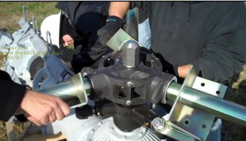
|
||||
| domwild Guru Joined: 16/12/2005 Location: AustraliaPosts: 873 |
Bruce, I do not know if Jacobs uses a roller pin. Dr Google would show the patent. Taxation as a means of achieving prosperity is like a man standing inside a bucket trying to lift himself up. Winston Churchill |
||||
| gpalterpower Senior Member Joined: 19/07/2009 Location: AustraliaPosts: 175 |
Hi all, As some of you probably know I am in the process of building a mill. At the moment I am up to the tail section which is a bit of a dark area for me. Ive been following midwoulds active pitch control for some time now(think it first popped up some years back ) and I gotta say Im fascinated by the idea. Watched your youtube fliks and would like to know more about the hub. What is the purpose of the 3 gears. dosent look like they are meshing with any others. Would it be possible to control a head like yours with some sort of spinning governor and return springs ect.? Im open for suggestions as I think there are more on the forum who are also interested. Bruce, do you have that drawing of the 3x cam operated head? Curious to see how it works. Marcus if it aint broke dont fix it!! |
||||
| Midwoud1 Newbie Joined: 25/12/2012 Location: NetherlandsPosts: 23 |
GP. Actually there is a 4 gear . A sunwheel and 3 satellite wheels. The sunwheel is free running on an extension nylon shaft in line with the mainshaft at the hubfront . The satellite wheels connected to the blade root shafts hook into the sunwheel. This is necessary the synchronize the blades. A spider linkage makes the blades move feather and unfeather. A push - pull rod from the spider through the hollow mainshaft to the actuator. That makes it an active pitch system. I have another system without gearwheels. A PVC tube with key-holes and a moving plug with 3 studs through the key-holes. The linkage connected to the blades. Blades move by a push-pull rod and actuator. Passive pitch-control. A spin governer with flyweights and springload like Janne made (Fieldlines) http://www.youtube.com/watch?v=rUcxmbLfu_U 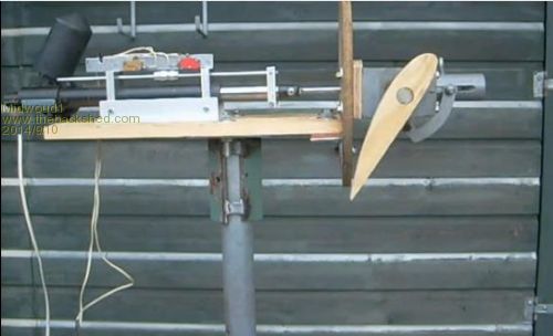
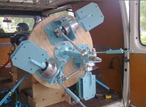
Rgds Frans (midwoud1) |
||||
| brucedownunder2 Guru Joined: 14/09/2005 Location: AustraliaPosts: 1548 |
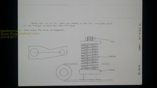
I received these drawings from a friend maybe 20 years back - I thank him and hope he does not mind me posting them here.2014-09-11_210147_bruce1.pdf 2014-09-11_210212_bruce2.pdf I hope someone can change these pdf files to a drawing , I can't , but maybe you can tell me how in a step by step proceedure,thanks Bruce Bushboy |
||||
| panky Guru Joined: 02/10/2012 Location: AustraliaPosts: 1101 |
Hi Bruce, Sorry to say, the PDF's have been "rasterised" prior to or as part of the conversion to PDF. That is, all the elements, lines, text etc. have been converted to a raster image. While it may be possible to re-construct, it would involve taking the PDF into a program like Adobe Illustrator then "tracing" the lines, text etc. A big job! Sorry I can't think of any way to assist. Cheers, Doug. ... almost all of the Maximites, the MicromMites, the MM Extremes, the ArmMites, the PicoMite and loving it! |
||||
| brucedownunder2 Guru Joined: 14/09/2005 Location: AustraliaPosts: 1548 |
Thank You ,Doug . My friend ,a drafting man, drew those drawings for me. Many years back . The principal is that the 3 shafts turn in hard plastic sleeves,similar to axle pin bushes. There is a cam welded to each and the blades can turn somewhat ,causing the cams to lift the bobbin at the base ,against a strong spring,adjustable,. When the wind becomes less forcefull, the spring action returns the blades to the original pitch.. Fairly straightforward to fabricate. One day I'll have a go . Bruce Bushboy |
||||
| gpalterpower Senior Member Joined: 19/07/2009 Location: AustraliaPosts: 175 |
Hi Bruce , Hope this helps Got to open files on my phone. Regards GP 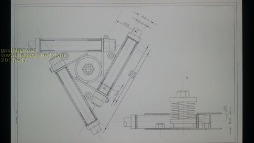
if it aint broke dont fix it!! |
||||
| Tinker Guru Joined: 07/11/2007 Location: AustraliaPosts: 1904 |
Fascinating, to see the complexity of some of the active furling ideas shown here. Unfortunately my idea for this is not yet up to demo stage so I won't publish anything of it at this stage. There are only 4 additional parts in total required for a full 90 degree furling of each blade shaft. I guess now I have to get cracking and machine these  Klaus |
||||
| jorn Newbie Joined: 30/12/2012 Location: NetherlandsPosts: 22 |
Every day homebuilders like Midwoud deliver us the evidence that also on small turbines active pitch control is the way to a safe well controlled machine. What do you mean complex? 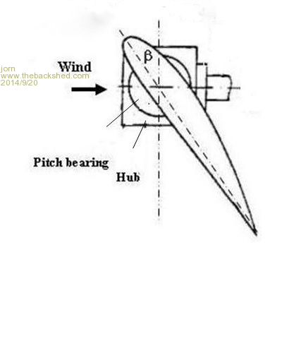
|
||||
| brucedownunder2 Guru Joined: 14/09/2005 Location: AustraliaPosts: 1548 |
First, thanks to Gpalterpower..(where do you guys get these names,lol.) Complex, Gee Klaus, there are only 4 moving parts. The spring could be a tappet spring for example. The rest of the fabrication is standard steel plate , 3X pieces of steel bar,3 common trailer axle bushes.. Me, I'm slowing down fast ,these days ,not the hypo active idiot I used to be. But, I'll give it a shot ,when I recover. Bruce Bushboy |
||||