|

|
Forum Index : Windmills : F&P Voltage Vs Rewire
| Author | Message | ||||
| leftcliq Regular Member Joined: 21/07/2012 Location: AustraliaPosts: 51 |
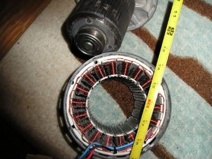
Hi Guys, I have been trying to decide as to which approach to take when rewiring the stator. I have a type 4 cogless motor. I'm wanting to wire to 24-30 Volts with 3 amps. My testing has proven that I am getting more voltage then what has been written on the FP-Rewire page. As an example, I am getting over 200V using the 2x6c setup. Is there a way to calculate the voltage and amps using a particular formula? I'm trying to decide if I should use the 4x3c setup or the 6x2c. I know it depends on the load but wanting to apply a formula before I rewire the stator. The load is a type 1 (I think) smartdrive motor (which I also have to rewire). Testing is being done by a rechargeable drill turning the rotor shaft. From my reading of the other forum posts, I have read that I can get approx .9 watt per rpm. Is this dependant on not having a load? Any thoughts, Dale. |
||||
| Warpspeed Guru Joined: 09/08/2007 Location: AustraliaPosts: 4406 |
Voltage depends on magnet strength, air gap, number of turns, and rpm. No real way to calculate, but pretty easy to measure. Once you know the voltage versus rpm for each winding, you can then figure out how to connect it all up to work under whatever conditions you plan to run it. Cheers, Tony. |
||||
Madness Guru Joined: 08/10/2011 Location: AustraliaPosts: 2498 |
Best way to test is with a 24 volt battery connected. With no load voltage will go very high, also there is no current flow. As the rewind page says 36Pole 4X3C is the way to go for 12 or 24 volts. Your 3 amps required should be achieved very easily. This is under 90 watts, sounds like you are planning a human powered generator. There are only 10 types of people in the world: those who understand binary, and those who don't. |
||||
| Gizmo Admin Group Joined: 05/06/2004 Location: AustraliaPosts: 5078 |
Hi Dale Voltage depends on RPM. Those voltages on the F&P rewire page are battery voltage when the F&P is used to charge batteries in a typical windmill application. So if you have a 24 volt battery bank for example, you can choose which rewire option should give the best results. Without a battery connected, you are going to get a much higher voltage, that will change as RPM changes. The faster you spin it, the higher the voltage. The battery acts as a voltage regulator of sorts. Watts IS dependant on load. You cant have watts without it been used in some way. Watts is the power used at the moment. Its like you car engine. It may make 100kW, but unless your driving it up a hill flat out, its not going to be making 100kW. Glenn The best time to plant a tree was twenty years ago, the second best time is right now. JAQ |
||||
| Gizmo Admin Group Joined: 05/06/2004 Location: AustraliaPosts: 5078 |
Just adding, powering a F&P with a battery drill and no battery load is a little dangerous. The 200 volts you read will kill you easily, so please be carefull. The best time to plant a tree was twenty years ago, the second best time is right now. JAQ |
||||
Madness Guru Joined: 08/10/2011 Location: AustraliaPosts: 2498 |
You will need to rectify the output also as the raw output is AC and it needs to converted to DC to connect a battery. You could put a 24 volt headlight bulb across the output with no battery or rectifier. This will allow you to get some idea of the output. There are only 10 types of people in the world: those who understand binary, and those who don't. |
||||
| daveames Newbie Joined: 19/09/2009 Location: United StatesPosts: 30 |
Hey Dale, Were you wanting to construct a battery charging mill or something like a mill directly AC coupled to another F&P motor? Most of these motors seem to behave 'linear' for the most part...meaning changing the ratio of one thing will give a predictable'ish outcome to the final. An example might help- at drill rpm X we have 200v at drill rpm 2X we have 400v at drill rpm 1/2X we have 100v same thing with the total coil turns per phase- at 2 x 6c we have 200v therefore we can guess with stock star windings of- 1 x 12c about 400v 4 x 3c around 100v 6 x 2c aprox 66v 12 x 1c should be 33v A bit more detail about your project might help folks understand what you are wanting to do. Cheers, dave |
||||
| leftcliq Regular Member Joined: 21/07/2012 Location: AustraliaPosts: 51 |
Hi Guys, Thanks very much for the replies. I am using a bridge rectifier to power a circuit with <30v. Hence, trying to get the right wiring configuration on the stator. Have considered using the 6x2C and will worked out I should get about 66v going by the sliding scale. The upshot of this is more amps. Drill speed for testing is 550 RPM approx. (checked with an RPM counter) Trying to achieve a stable 24V at 3-5amps DC at 200-300 RPM. If I can get this I will be a happy camper. The aim is to have this hooked up to a DC - AC inverter powering a load of lights etc or a battery bank. Of course RPM is variable. Currently, have a Type 4 36 pole STAR smart drive motor. Can you please send me the wiring image for the 12 x 1c, cannot seem to find this image on the fprewire. Going by the name, sounds like I wire the 3 coils, one end of each coil together and the other is the input to the bridge. Is this created at 200-300 RPM? At 33v, this should generate a large amount of current? Going by the sliding scale, I would estimate somewhere close to 6 amps? 
Thanks guys again for all of your input and I look forward to more discussion re this. Also, I hope this helps out someone else in the future who may have the same dilemma. Also thanks for the safety advice and the light bulb load idea. Regards, Dale. |
||||
| yahoo2 Guru Joined: 05/04/2011 Location: AustraliaPosts: 1166 |
Handy Formula to calculate the output of any generator at any given RPM http://www.windstuffnow.com/main/generator.htm I'm confused, no wait... maybe I'm not... |
||||
| leftcliq Regular Member Joined: 21/07/2012 Location: AustraliaPosts: 51 |
Hi Guys, Does anyone have the wiring image of the 12 x 1C ? Want to make sure I do things right. Thanks, Dale. |
||||
| leftcliq Regular Member Joined: 21/07/2012 Location: AustraliaPosts: 51 |
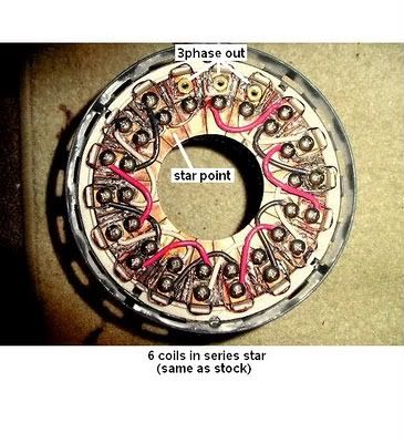
Hi Guys, Here is what I think the 12x1c should be wired up. Can someone please let me know if they think its correct? Regards, Dale. |
||||
| daveames Newbie Joined: 19/09/2009 Location: United StatesPosts: 30 |
Hi Dale, Nice job on the sketch. 
Afraid I'm still not sure what you're up to with these stray bits of equipment? Couple things stand out from here. Your numbers show an open voltage* of about 12v to 18v at 200 to 300 rpm using 12x1c. If the plan includes trying to run the rectified dc into a standard dc-ac inverter, Then time for a new plan. 
Really need to go..Alternator->Rectifier->Battery->Inverter->Lo ad. Then some kind of charge control in parallel with the battery. Great Fun! Cheers, dave *Open voltage, ..we need to get at least up to and past this voltage to begin any kind of charging in a battery system. Did you get a chance to browse that windstuffnow info? Pics? Edit: try to correct some strange spacing..Preview post function not working? |
||||
| leftcliq Regular Member Joined: 21/07/2012 Location: AustraliaPosts: 51 |
Hi Dave, I know the diagram is a bit rough and was done in haste but I think the connections are correct. From my sums and testing of other wiring setups (and your reply above), 12x1C should generate an open voltage of 33 Volts at 6 Amps at 200 RPM. Am I wrong in this? I thought this will be enough open voltage to be useable? The design is there to charge a battery and the load is ran from the battery. I was going to seperate each coil and use terminal blocks so I could rewire the smart drive motor as needed in any case. I'll check the resistance of the coils. Yes I checked out the windstuffnow pages. There info was based on the 42 coil smart drive. I will re-read it in case I missed something. Reagrds, Dale. |
||||
| daveames Newbie Joined: 19/09/2009 Location: United StatesPosts: 30 |
Sounds like a good plan Dale. A field configurable stator adaptable to lots of applications. Done a couple of the GE ECM'S (sort of an inside out F&P)..makes going from waterwheel to windmill to ped gen real easy!..just keep changing the coil set-up till it works the way you want. 
A good tip here is to leave the coil starts (the buried end) extra long when you cut it and unwrap one turn on the finish end to have enough tail to work with. Here's what those GE motors look like: 


Only 18 coils on these but not much room under the end bell...Looking at my F&P it seems easy enough to epoxy some terminal connectors along the inside rim of the stator.. Fun stuff! dave .... .. KB1MZF |
||||