|

|
Forum Index : Windmills : Voltage Confusion
| Author | Message | ||||
wallablack Senior Member Joined: 10/08/2011 Location: AustraliaPosts: 164 |
I have caused myself some confusion due to over researching. A year ago I fitted a Chinese 200W mill to a Powerjack GTI via a 100A 1000V Rectifier. This has worked well and is still going strong. Then I got the bug. I purchased 2 x 120W solar panels to run through the cheap GTI alongside the mill. Then I proceeded to build my F&P mill. Questions.... On bench testing my mill with a power drill it obtained 24 volts at a very slow speed, I upped the drill speed to a realistic "blade speed" and it was producing 100V DC. In my curiosity I got the drill going flat stick and the mill was producing 260 V DC...yes DC. I haven't tested for amps yet. My question is...I will be running it to a bridge rec like THIS This will convert AC into DC. My usual wind speed is between 5 and 10 m/s so it will be producing 12V plus. If it was to run and produce say 100V DC for arguments sake how do I drop this to a more usable voltage? I have three inverters which INPUTS are: 7-24V, 20-38V, and 48 - 96V. These values arent exact but pretty close. Too early to go to the shed and check or too lazy... Foolproof systems do not take into account the ingenuity of fools. |
||||
| Greenbelt Guru Joined: 11/01/2009 Location: United StatesPosts: 566 |
wallablack HI, You must first apply a load to the output to determine the system working Voltage, A rectified AC voltage will show peak to peak volt on a DC Voltmeter when no load is used. The true Volts will be, (Voltage * 0.707 ), or less. Example, Your indicated Volts flat out, 260 * 0.707 = 183.82 A load is needed to find your output value. Welcome to the Forum, best of times ahead for you. --------Cheers, Roe Time has proven that I am blind to the Obvious, some of the above may be True? |
||||
| larny Guru Joined: 31/10/2011 Location: AustraliaPosts: 346 |
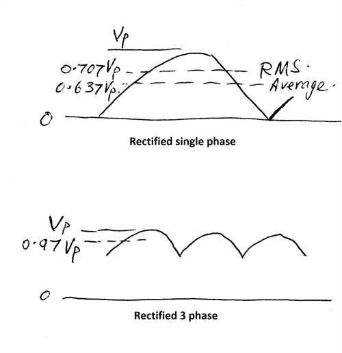
Yes, I agree you need a load. However, the Multimeter reading depends on the meter. For example, I have a DMM that reads the true RMS voltage, ie. it will calulate the RMS of any waveform - not only sineusoidal signals. And an analogue (ie. moving coil) meter will read the average voltage. From memory, the average of a rectified sine wave is 0.637 of the peak. So if it reads the average then the voltage would be 260/0.637 = 408 Volt. But I doubt if that is a case in your situation. Len |
||||
| Warpspeed Guru Joined: 09/08/2007 Location: AustraliaPosts: 4406 |
It's a bit like revving up your car engine up when it is out of gear. With no load, the voltage will go very high. With a battery connected, the voltage will only rise up to the battery voltage, and go no higher. But then the current will start increasing quite quickly once you reach that point. Cheers, Tony. |
||||
| BobMann Senior Member Joined: 30/06/2011 Location: United StatesPosts: 134 |
You should take a look at my post Low cost F&P using the Smart Controller These F&P can snap high Volts just in 1/4 of a turn. So there ar few ways to go right into a battery bank that a grid tie inverter. Or a controller to grid tie. Bob Mann |
||||
| turnymf Regular Member Joined: 04/10/2008 Location: AustraliaPosts: 84 |
Shouldn't that be 260 x 0.637 ? If the 260 was ac how do I drop this to a more usable voltage? You could try rewiring the stator for lower voltages |
||||
| larny Guru Joined: 31/10/2011 Location: AustraliaPosts: 346 |
Actually that is what I wrote first. But, after posting, it dawned on me that if the meter is reading 260 Volt & that is the average, then the peak would be 260/0.637. However, that assumes that he was measuring a 1 phase rectified sinewave signal. It will be different if he was measuring a rectified 3 phase signal. I don't know what the average of a rectified 3 phase signal is & really don't feel like doing the maths. Len |
||||
| Warpspeed Guru Joined: 09/08/2007 Location: AustraliaPosts: 4406 |
Average and RMS will be so close together it does not matter. Both will be about 3% less than the absolute peak of the ac voltage. Cheers, Tony. |
||||
| turnymf Regular Member Joined: 04/10/2008 Location: AustraliaPosts: 84 |
Now I'm confused I thought that peak was half peak to peak Rms was peak x 0.707 |
||||
| Warpspeed Guru Joined: 09/08/2007 Location: AustraliaPosts: 4406 |
You are right. Rectified single phase: RMS is 0.7071 times peak. Average is 0.637 times peak. Rectified three phase: RMS and average are very close to being the same at around 0.97 times peak. Cheers, Tony. |
||||
| larny Guru Joined: 31/10/2011 Location: AustraliaPosts: 346 |
A picture is worth a 1000 words. See below. Len 
|
||||
| larny Guru Joined: 31/10/2011 Location: AustraliaPosts: 346 |
If it was to run and produce say 100V DC for arguments sake how do I drop this to a more usable voltage? Another way you could do it would be to use a transformer. If you can't buy, beg or steal a suitable 3 phase one, it could be done with three single phase transformers connected either in Star or Delta. Their secondary windings would also be connected either in Star or Delta with your rectifier bridge connected to them. |
||||
wallablack Senior Member Joined: 10/08/2011 Location: AustraliaPosts: 164 |
It is currently wired 2 x 7C. 
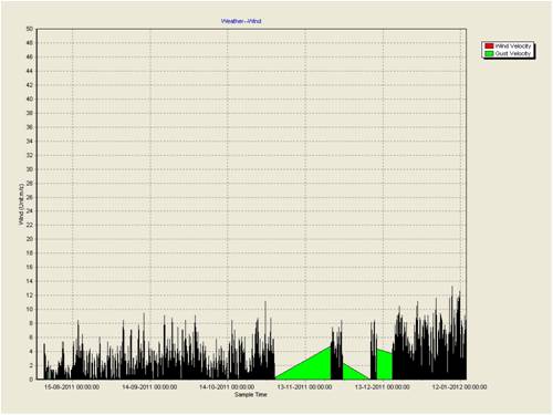
What wiring configuration would members recommend for my wind pattern? I am deciding between a VWAT or a HWAT. I have a 200W VWAT at the moment, it doesn't dance around in the wind giving indication the wind isn't very turbulent, the reason for a HWAT is purely for a learning curve. EDIT: The wind speed on the vertical axis is in m/s (metres per second). Foolproof systems do not take into account the ingenuity of fools. |
||||
| Don B Senior Member Joined: 27/09/2008 Location: AustraliaPosts: 190 |
Hi Wallablack On the matter of the prospective output from your alternator, you will only get a realistic indication of what it can do when it is connected to a load. Ideally, the load should include the rectifier and battery that you plan to use. You then need to simultaneously measure amps and volts. When you spin an alternator with no load, you are only measuring the open circuit voltage. When you have a load connected, this open circuit voltage drives current through both the load, and through the internal resistance of the alternator itself. The voltage drop caused by current flowing through the internal resistance (impedance, actually) of the alternator subtracts from the open circuit voltage, so that what you will then be measuring is the terminal voltage of the alternator operating under load, and it is always less (sometimes much less) than the open circuit voltage. For maximum power transfer from the alternator's mechanical input to the load, the load resistance has to equal the alternator's internal resistance. This means that roughly half of the alternator's open circuit voltage is dropped across its internal resistance, and its terminal voltage will therefore be about half of its open circuit voltage in this situation. AS noted previously in this thread, when the load is a battery, the output voltage is locked to the battery voltage, making the load effectively a variable resistance that reduces as the charge current increases. You therefore rarely get the situation where the load and the alternator resistances are equal, so that you get less than maximum power transfer. Even so, this is the way that standard alternator/rectifier/battery arrangements operate. Concerning the relative merits of horizontal and vertical axis wind turbines, the important distinction is between drag and lift type turbines. Drag type turbines are always less efficient in converting wind to mechanical energy, and most vertical axis turbines are drag type turbines. Lift type vertical axis turbines also tend not to be self starting. Another significant factor is turbulence. The closer to the ground and/or upwind obstacles your turbine is, the more turbulent and generally slower will be the incident wind, and the less power you can produce. You need to go for as much height and the cleanest air as is practicable. I suggest that you have a good browse through other threads in this forum, also the feature articles, as they contain a wealth of helpful information. Regards Don B |
||||
wallablack Senior Member Joined: 10/08/2011 Location: AustraliaPosts: 164 |
Thanks to everyone for your input. It has been more than uselful. This forum has helped me out a lot and I will continue to research on here in the future. Foolproof systems do not take into account the ingenuity of fools. |
||||
| larny Guru Joined: 31/10/2011 Location: AustraliaPosts: 346 |
I just discovered a useful link in another forum. It includes 3 phase rectification. http://en.wikipedia.org/wiki/Rectifier#Full-wave_rectificati on Len |
||||
| Warpspeed Guru Joined: 09/08/2007 Location: AustraliaPosts: 4406 |
Good link Larny. You can see why a three phase full wave bridge puts out such a high dc voltage. All the half cycles overlap, keeping the dc output right up near to the absolute peak of the ac voltage.  Cheers, Tony. |
||||
| larny Guru Joined: 31/10/2011 Location: AustraliaPosts: 346 |
Yes, it shows why the average voltage is about 97% of the peak. Len |
||||