|

|
Forum Index : Windmills : Recycled Items used to generate power.
| Author | Message | ||||
MrDelanco Senior Member Joined: 12/11/2011 Location: United StatesPosts: 101 |
Hello Niall; The Motor-Generator-Flywheel ups unit is a subsystem I built from several other designs built into one unit. I been building it for 2-3 yrs. It consists of three(3)large diameter gyroscopes with a motor-generator flywheel suspended in the center, the flywheel is 3 feet in diameter and weighs 600 lbs. I used recycled items to build it from a bank vault I removed during a renovation project. With no power driving it the flywheel will start to move and spin very slowly at a 23 degree natural tilt to levelness of it's position. I noticed this after I finished balancing the flywheel and left it sitting overnight. I found it rotating very slowly the next day when I came in to continue working on it. I am still tweaking the Motor-Generator-Flywheel ups but it is operating in the system. The motor engages with pulses from a trigger, once momentum is achieved it requires very little energy from outside to continue it's motion. There are pem's mounted to the flywheel and a stator with coils from the center to the perimeter of the platter. It continues to tilt off center by 23-25 degrees depending on the time of the year. It is not easy to stop the unit to preform upgrades. I am not completed with the build of the unit so I was not posting much info about it, I slip up in the other post, I was not ready to bring it out in the open. Regards Robert. MrDelanco:Project Videos It is not only too know what it does but to understand how it does what it does. |
||||
MrDelanco Senior Member Joined: 12/11/2011 Location: United StatesPosts: 101 |
Hello all; Merry Christmas and Happy new year; Over the past few weeks I been working with magnetic bearings will post my information as soon as I get some free time too compile it. All the best to everyone , Regards Robert. MrDelanco:Project Videos It is not only too know what it does but to understand how it does what it does. |
||||
| Doc Cox Newbie Joined: 04/01/2012 Location: United KingdomPosts: 2 |
Do you have any more in depth electrical circuits for your set up and dimensions of the turbine please, regards Doc Cox  |
||||
| WindyMiller Regular Member Joined: 05/04/2011 Location: United StatesPosts: 62 |
On the subject of flywheel storage systems. http://www.free-energy-info.com/P25.pdf I personally find the idea interesting and cannot wait to hear more about your setup MrDelanco. Robert |
||||
| Throgdor Newbie Joined: 26/01/2012 Location: United StatesPosts: 22 |
MrDelanco. I have viewed several of your short video's and generally like what I see with your giromill. However I can not figure out or see how the Tail is mechanically attached to the blades. All I see is a "tail" off to the side of the main vawt. I'd love a general blueprint or diagram of this. The 14 to 1 ratio sounds and looks impressive on the video's. Throgdor / Mark |
||||
MrDelanco Senior Member Joined: 12/11/2011 Location: United StatesPosts: 101 |
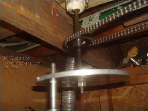
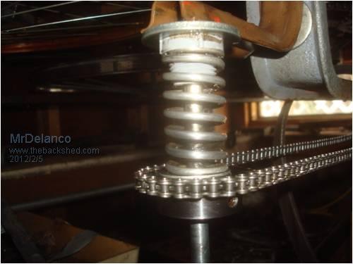
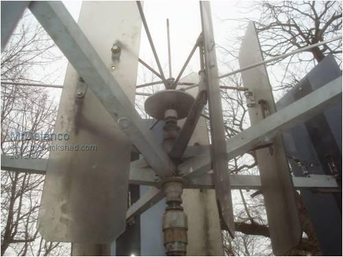
Hello Mark; The top of the mill has an off-set cam plate that is attached too a 3/8" rod run down inside the 3/4" drive-shaft that runs inside the 2" support pole. The inside end has a sprocket and chain run to another spring loaded sprocket on a 3/8" shaft with another sprocket and chain run across the ceiling around two more sprockets too adjust the chain tension then to another sprocket attached to a 1/2" shaft running up inside the 1" tail support pole. Regards Robert. MrDelanco:Project Videos It is not only too know what it does but to understand how it does what it does. |
||||
| WindyMiller Regular Member Joined: 05/04/2011 Location: United StatesPosts: 62 |
Just wanted to post the working link for those who could not get it to load. Link Robert |
||||
MrDelanco Senior Member Joined: 12/11/2011 Location: United StatesPosts: 101 |
Hello Mark; The top of the mill has an off-set cam plate that is attached too a 3/8" rod run down inside the 3/4" drive-shaft that runs inside the 2" support pole. The inside end has a sprocket and chain run to another spring loaded sprocket on a 3/8" shaft with another sprocket and chain run across the ceiling around two more sprockets too adjust the chain tension then to another sprocket attached to a 1/2" shaft running up inside the 1" tail support pole. Here are some photos 


MrDelanco:Project Videos It is not only too know what it does but to understand how it does what it does. |
||||
MrDelanco Senior Member Joined: 12/11/2011 Location: United StatesPosts: 101 |
Hello Everyone. Well the cycloturbine made it through the storm with a 10 out of 10. Battery banks are over-charged but we will use it up. Didn't think the desk chair base legs would hold but they are still attached to the mast and the blades are still intact. The system held its ground and didn't fail. The wind took down lots of trees and power lines all around us, I watched the cycloturbine spin fast and stop then spin fast in the other direction and stop. The inner set of blades did what they were suppose to do, act as air brakes in high winds. All in all we still have power and are still making more. MrDelanco:Project Videos It is not only too know what it does but to understand how it does what it does. |
||||