
|

|
Forum Index : Windmills : mini dual axial flux Wind Generator
| Author | Message | ||||
Bryan1 Guru Joined: 22/02/2006 Location: AustraliaPosts: 1344 |
G'day Guy's, With those remaining 16x13mm round N50 neo magnets I had left I decided to make a mini dual axial. I had just the right amount to do a 16/12 config and put 2 magnets for each pole so that makes 32 magnets on each disk. Yesterday I cast the front magnet rotor with epoxy and due to the cold weather here I'm going to leave it a week before putting it in the lathe to machine true. The pic below shows the autocad drawing and the bolt centre in the pic is 100mm but I reduced it to 76mm so I can fit bigger coils in. With each magnet rotor I machined in a 0.4mm spotface for ach magnet pole to ensure the magnets are mounted spoton. Each magnet rotor disk is 200mm diameter and once both magnet plates are cast and machined I'll throw up some pic's. I had that spare drum brake hub here and it worked out purfect for size so I'll be using that. As far as blades go I reckon 1.2 metres diameter gives the best output in Altons Wind Calculator so I'll wind the coils to suit that. For the test coil I'll use 1mm magnet wire but if I can fit 1.6mm (14awg) wire I will for the final stator. The output goal for this small dual axial will be around 500-600 watts for a 24 volt array. The only real expense will be for some polyester to cast the stator and I'm going to cast in a thermistor to monitor temps. If the temp goes above 65C then my circuit will short the genny until it cools to ambient temperature. As the neo's are only rated to 80C and epoxy about the same if the temp does rise then my little circuit will come into action. 
Cheers Bryan |
||||
| VK4AYQ Guru Joined: 02/12/2009 Location: AustraliaPosts: 2539 |
Hi Bryan Looks good mate it will be interesting to see how it compares to Glens machine as it is similar size. All the best Bob Foolin Around |
||||
| Gizmo Admin Group Joined: 05/06/2004 Location: AustraliaPosts: 5078 |
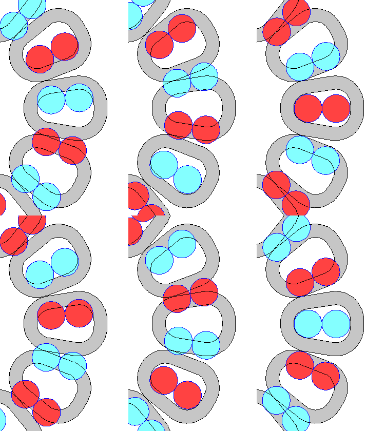
Looks good Bryan I would make the coils bigger, the space between them is wasted otherwise. Also I would try to keep the coil inside diameter larger that the magnets, even if just 1 mm or so. If you impregnate the coils with epoxy/resin as you wind them, that will be rock solid, very strong and a structual part of the stator. The 2 magnets side by side will want to push apart, I used a cable tie around each pair to hold them together while the epoxy set. Heres a close up and animated graphic of my coil/magnet layout, showing 3 phase coils. 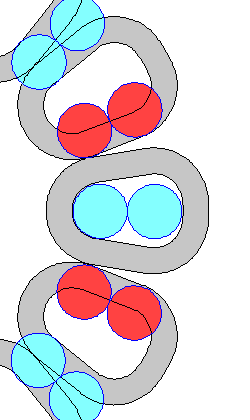
Glenn The best time to plant a tree was twenty years ago, the second best time is right now. JAQ |
||||
MacGyver Guru Joined: 12/05/2009 Location: United StatesPosts: 1329 |
Nice drawing Bryan. I've put it into my archive and will refer to it often. I too am in the process of building a mini ax-fx, but mine is a mere toy. I don't expect any more than about 100 watts from it if that. I've built several in the past, which have all become fancy paper weights. The current one uses a lot of "short cuts" but I am pretty sure it will fly. I'm using a bicycle front hub for the axle, so you can guess at the rest of the dimensions. The blades are Coroflute and one meter each. I'll post a build album when it's up and running. Edit: Glen, you snuck in just as I posted. I like your drawing and animation as well. Here's a similar animation I got from Oz back in the day. . . . . . Mac Nothing difficult is ever easy! Perhaps better stated in the words of Morgan Freeman, "Where there is no struggle, there is no progress!" Copeville, Texas |
||||
| shawn Senior Member Joined: 30/03/2010 Location: New ZealandPosts: 210 |
Look forward to seeing the mill Bryan these small mills seem to be fun I must try one sometime! Also when you get back to your big motor conversion you must post it for us to see. Shawn |
||||
Bryan1 Guru Joined: 22/02/2006 Location: AustraliaPosts: 1344 |
G'day Guy's, Bit of an update, last weekend I tried epoxying in a mag plate only to find the epoxy didn't go off so I ripped out all the epoxy and started from scratch using fiberglass resin. I used some stupid glue (well loctite instant adhesive) to hold each magnet in place. The wooden island is made out of some 16mm MDF which I painted with some motor varnish to fully seal it then greased so hopefully once the resin is fully set it will just pop out. The magnets are 13mm thick so I do have a machining allowance to face the resin to true it up. Todays job is making up the coil winder and working on the hub. Well getting there slowly..... 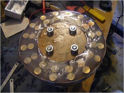
Cheers Bryan P.S. Glenn that cad image of the coils was just for the sim and I will be making the coils so they are a tight fit. I will wind the first test coil out of 1mm magnet wire but I am hoping to use 1.6mm wire. The turns will dictate what wire I use. |
||||
| Greenbelt Guru Joined: 11/01/2009 Location: United StatesPosts: 566 |
Bryan1 Hi  , ,
I saw a pictorial post today on Randys workshop and thought about the work you have in progress, so far looks like a good start. I've seen some projects on this forum that suffered the same mistake that randy made when building his Axial Alt. After he corrected that problem, results were outstanding. You may be aware of this pitfall but I'm offering this heads up. would like to see some major output 
Quote from Randys workshop After consulting other experts in the field, it was determined that my coil was the wrong size for my magnet. The magnetic field should pass through the straight side of the coil. Passing over the curved area reduces the induced current. The above image shows the revised coil.. End Quote. Scroll down 2/3 on the link page to see the change in design. ----------Cheers, Roe Time has proven that I am blind to the Obvious, some of the above may be True? |
||||
| Gizmo Admin Group Joined: 05/06/2004 Location: AustraliaPosts: 5078 |
Yeah Bryan I didn't have much luck with epoxy either. When I made the coils I made very little effort to get the 5:1 mix right, a blob of epoxy and a splash of hardener, and they all set hard. But the mold was another matter, even though I was carefull about getting the mix right. The final layer didn't go off at all and I had to dig it out. I think resin is the way to go. Glenn The best time to plant a tree was twenty years ago, the second best time is right now. JAQ |
||||
| Tinker Guru Joined: 07/11/2007 Location: AustraliaPosts: 1904 |
Glenn, you can get epoxy in many different mix ratios. Try a 2:1 mix next time, its *much* easier to get exactly right. I hope you did remember that CSM (Chopped strand mat) is incompatible with epoxy resin. You must use only woven glass cloth or tape. I hope that was not the reason for your 'not go off' problems. I still believe ordinary fiberglass resin is a poor choice for coil encapsulating. Larger quantities can get too hot, it 'goes off' rapidly with plenty of opportunity to trap unwanted air bubbles. The slow hardening time of epoxy resin is much easier, IMO, to control, use either slow or fast hardener depending on the ambient temperature. It gives a long working window, long enough to set up a vacuum to extract any trapped air bubbles. Klaus |
||||
Bryan1 Guru Joined: 22/02/2006 Location: AustraliaPosts: 1344 |
G'day Guy's, Bit of an update, I machined both mag rotors in my big lathe to true them up and they turned out fine. I have painted them so far with 2 coats of epoxy paint and today I'll see if the paint is hard enough to move forward. The next step is fabricate the stator mount out of some 6mm plate and install it on the hub array. I still have the stator mold to make and I will need to make that before I start on making the test coil. So getting there.... Regards Bryan |
||||
Bryan1 Guru Joined: 22/02/2006 Location: AustraliaPosts: 1344 |
G'day Guy's, Well I canned using the drum brake hub as while chatting in irc I did say I had a 750 kg trailer hub here. Anyway I went and checked it against my magnet rotors and I only needed to machine the outer casting on the front bearing to the rear rotor. While I was there I machined down the OD to just under where the holes were so it's nice and compact. I cut the extra off the 45mm square butt on the stub and I have some 40mm solid square bar here so I'm going to cut a length and set it up @ 45 degrees to give me more tower clearance. I cut 4 off 25x10mm lengths of flat bar for the stator mounts and tapped M16 holes in them for the stator. I will be using M16 grade 8 all thread for holding the stator which should hole the stator in place when the brakes are applied. Under my bench was a 355 mm OD MDF disk so I marked out the pcd then bolted all 4 struts then welded them onto the stub. This ensured that all the holes were lined up and each strut was welded nice and square. I went over to my pile of hydraulic pipe and found some heavy walled pipe that is a neat sliding fit so that solved my drama's on how to make the final genny mount. Tomorrow I'll cut the pipe and that 40mm square bar and get the genny mount all finished then it's time to make a start on the coil winder. I've made the stator mold and marked out a sheet of drafting paper so when I place it down in the mold where I marked out and drew the magnets I can see thru the film and check the placement of the coils which is handy. I did the sums to get the maximum wire in the stator and it does look like I can go atleast 2 in hand. I'm going to use 1mm wire 2 in hand for the first coil test and I might even try a 1.6mm 2 in hand coil too. Depending on the turns I need for 24 volts I am hoping to use the 1.6mm wire to get the Ohm's right down. Roe I did checkout that link you gave but I am thinking as I am using 2 round neo's on each pole by going smaller on the inner and larger on the outer of the coil might cause some cancellation so a straight oval coil might work the best for this genny. I will try with both shapes and check to see there is any cancellation. Anyway the batteries on the camera are flat and tomorrow I'll get some new ones and take a few to show my progress on this mini genny. Cheers Bryan EDIT: Silly me should of looked at the great job Glenn did on the animated pic and Yes I will try the shape he did in that pic. Also I will do a straight coil and see if there any difference. |
||||
| Greenbelt Guru Joined: 11/01/2009 Location: United StatesPosts: 566 |
Bryan1, Hi  I see your logic on the oval coil shape, Its difficult to get the required turns in a small radius. I see your logic on the oval coil shape, Its difficult to get the required turns in a small radius.
And yes, Glen has maximized the available space. This wedge shape helps the timing of the 2 Mags to cross the legs at the same time which should contribute to a better wave form. If the inner mag crosses the coil leg slightly earlier than the outside one and is slightly later crossing the other leg, this would flatten the wave sine probably causing a small voltage drop as if the rpm were slower than the outside mag. Just thinking out-loud. You are doing a great job. ---------Cheers, Roe Time has proven that I am blind to the Obvious, some of the above may be True? |
||||
Bryan1 Guru Joined: 22/02/2006 Location: AustraliaPosts: 1344 |
G'day Guy's, Got a bit of time before the grand final this morning so I welded up the genny mount. The pipe is 60mm with 5.5mm wall thickness and the inner pipe has about 0.035" clearance. I found a sealed ball bearing just the right size so I'll use that as the yaw bearing. There is just over 5"'s offset from the centre and I put a 6 degree up slope so the blades will have plenty of clearance. 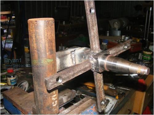
Here's a pic of the finished front magnet rotor 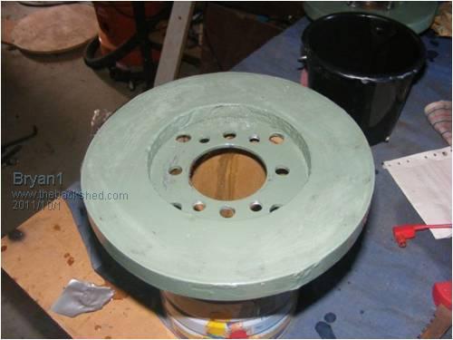
And here's a pic of that 750 kg trailer hub I machined down 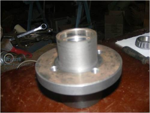
Tomorrow I'll finish off the fabrication and make a start on the coil winder Getting there...... Cheers Bryan |
||||
Bryan1 Guru Joined: 22/02/2006 Location: AustraliaPosts: 1344 |
G'day Guy's, Well got the genny assembled ready for the single coil test and making the coil winder is next on the list. This morning I cut the old tail of my old F&P genny and it's just the right size to re-use. 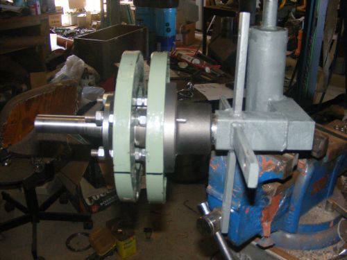
The steel spool on the end is for holding the blades and I'll use a conlock like I did with my 1.5Kw motor conversion. With a bit of tweaking I got the shaft running within 0.003" too which I was very happy with. Now for the yaw bearing I used a sealed ball bearing and made the top plate with a 3mm shoulder to locate the bearing then machine a 2 mm shoulder so it will contact the inner race. I welded it on the pipe and the genny mount swings nice and freely and when I grease the tube it will also run nice and silent. Not shown is the O-ring groove I machine in lower part of the main pipe, not only hold hold the grease in but also to help keep the pipe square for the bearing. 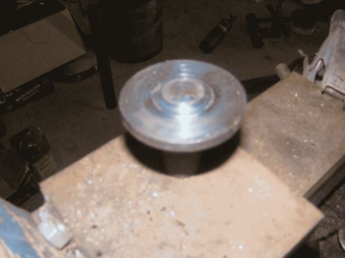
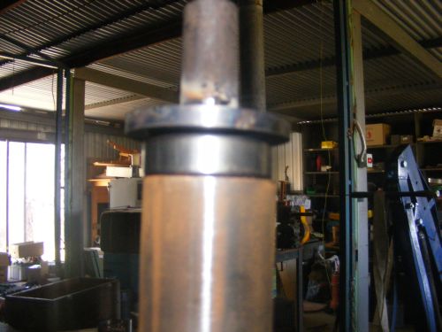
hopefully this afternoon I can get a coil made up and finally start doing some tests. Regards Bryan |
||||
| shawn Senior Member Joined: 30/03/2010 Location: New ZealandPosts: 210 |
The pictures look good Bryan it will be interesting to see what wire you can fit in there? |
||||
Bryan1 Guru Joined: 22/02/2006 Location: AustraliaPosts: 1344 |
G'day Guy's, Well for most of today I was trying different test coils and finally ended up making one with 60 turns out of some old Seeley magnet wire I have here. Soon after I fired the motor up I was seeing 6.2 volts and it didn't look to going that quick so I started taking measurements at different speeds and finally worked it out to about 300 rpm cutin for the 60 turn count. I also decreased the air gap form 17 to 15 mm and did see a nice jump in voltage when I was trying the 27 turn test coil. I made 2 of the 27 turn ones. One was straight oval and the other a wedge shape and the wedge shape did produce a slightly higher voltage at the same rpm. For making the coils I just made a simple jig out of some MDF and clamped with a 6mm bolt, then put the jig in my toolroom lathe and manually counted the turns. In order to keep the coil together and aid with removal I put in 2 off 1mm bits of wire then once the coil was done I twisted the wire to keep the coil shape. Then carefully with a jewelers screwdriver I prised up the coil from under the 1mm wire then just taped the coil tight with some insulation tape. Now my ultra crude way of doing the speed test was using my 50 volt DC motor hooked up to my 30 volt bench psu and made a belt out some plastic pipe held together with some 1mm magnet wire. The motor has a jaw coupling on so I ran the belt off that and by changing the voltage I was able to get data at 50 rpm intervals all the way upto 1100 rpm. 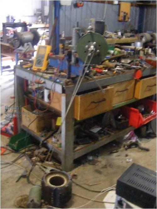
As shown in the pic the belt is tensioned using the 4Kw motor conversion body holding the DC motor at tension. I cut up some plexiglass for the test coil holder and just a hot glue gun to attach each coil to it. 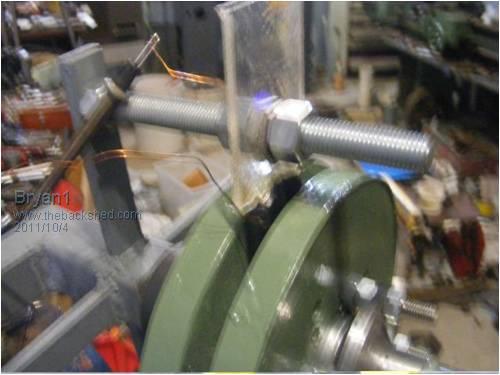
The wedge coils I made all had a bigger hole then the magnets so in the morning I'm going to make a smaller jig and hopefully I can get 60 turns of 1mm (18awg) wire to fit in. The original mold I made was 14mm thick and i've decided to make a new mold thats 10mm thick so I can get the air gap set at 13mm and that should increase the flux even more. Regards Bryan |
||||
Bryan1 Guru Joined: 22/02/2006 Location: AustraliaPosts: 1344 |
G'day Guy's, Anyway got the stator all cast and rather post all over forums with my project I'm just doing the full write on the new AnotherPower Forum. Glenn I hope you mind me posting a link but here it is. http://www.anotherpower.com/board/index.php/topic,78.msg401. html#msg401 Regards Bryan |
||||