
|

|
Forum Index : Windmills : Requesting selecting wire size for stator
| Author | Message | ||||
MrDelanco Senior Member Joined: 12/11/2011 Location: United StatesPosts: 101 |
Hello Lauri If your in the USA and are in NY do you have two(2) or three(3) phase from the power grid where you live ? Does your needs require three(3) phase ? Are your stators in sync or are you slightly out of sync ? Is one set of coils fighting with the others for phase control ? Are you feeding back into the other coils with your 1st charge ? The wiring diagram above show's a feed back into the other coils that could be energizing the coils and causing drag inside the pma circuit. Each phase level should be separate from each other and run into it's own rectifier, then joined into one after rectification of each level. Then run into the charge controller, then the batteries. Regards Bob MrDelanco:Project Videos It is not only too know what it does but to understand how it does what it does. |
||||
| govertical Guru Joined: 11/12/2008 Location: United StatesPosts: 383 |
Hi, this forum is a great asset. It provides a opportunity for many different people from many different locations to share and discuss information. When communicating with the given media it is easy to misinterpret intended meanings. It is not my intent to create a adversarial situation. I apology to all if this appears to be happening. When considering a 3 phase single stator with dual rotors is there a connection from the negative post of the battery to the common center connection of a star configuration? just because your a GURU or forum administer does not mean your always correct :) |
||||
| yahoo2 Guru Joined: 05/04/2011 Location: AustraliaPosts: 1166 |
I apologise if I have confused the issue, the point I was trying to make was that the commercial 3 phase alternators ONLY have a wire to the common centre connection for a safety measure if there is a field fault, in a machine like an engine driven welder some have 4 pairs of diodes to rectify AC , three fields and this safety wire are connected. In a single stator turbine it is not needed, does not carry any power or play any part in the operation of the PMA. The fact that connecting the black wire in your diagram is changing the driving resistance says to me that your PMA is not running correctly. I think what greenbelt is asking with this diagram. Do you have each phase of a single stator wired the same way. that is with wire A,B and C connected to the rectifier diodes, if you have then as the rotor turns power generated in one field will be partially cancelled by power generated in the other two fields in the opposite direction. The picture says that A,C and E are wired to the diodes and the rest to the common star connection. 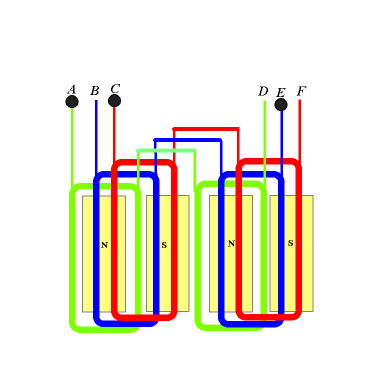
Unless greenbelts question can be answered its going to be tough to move on from this. ON PARALLEL STATORS Conventional wisdom would say separate stators each having their own rectifiers and absolutely no connections at all from one stator to the next so there is no possible chance of interaction of the AC between them. keep at it  yahoo yahooI'm confused, no wait... maybe I'm not... |
||||
| Greenbelt Guru Joined: 11/01/2009 Location: United StatesPosts: 566 |
Govertical wrote It looks like you are redrawing my diagram to illustrate a problem when there is no problem. end quote. This was bad judgment, It won't happen again. My thanks to MrDelanco and Yahoo2 for the input. Note; An electric generator of any kind supplies its own electrons and does not require a connection to a battery to supply power. If a circle or circuit exists within the machine then the current rolls like a wheel round and round and never comes out to power anything. it just causes heat and many times destroys its self. The circuit must not close until the load is connected as a chain link. any link that is not a part of the useful load is a short. The reference to the overlapped coils was to give you a clue. when polarities are reversed it causes problems. Your Stator links , To put it bluntly, are allowing currents to flow haphazardly out of phase and wrong polarity. this concludes my posts on this thread. Have a good Day.-------------- Cheers,Roe Time has proven that I am blind to the Obvious, some of the above may be True? |
||||
| govertical Guru Joined: 11/12/2008 Location: United StatesPosts: 383 |
Hi, not the best drawings but the first shows a single stator star connected to a diodes. The next shows the connections using three stators. The coils are aligned vertically. As I added more stators the required cut in RPM decreased by 100. At this time I believe tests results can be improved by increasing blade size and improving stator coils. Thanks for the information. This is a experiment and a first attempt. just because your a GURU or forum administer does not mean your always correct :) |
||||
MrDelanco Senior Member Joined: 12/11/2011 Location: United StatesPosts: 101 |
Even though the coils are aligned vertically it would help to separate them into their own bridge rectifier's for each stator then bring them into one output. Don't join them in the middle go from output of one coil to input of the next coil. The way you wired them will only give you one coil output per three(3) coil's so you are wasting the other two(2) coil's function of adding too or building to a higher voltage. If one coil output is five(5) volt's and you connect three of the coil's in parallel as you are showing, you are only going to get five(5) volt's. If one coil output is five(5) volt's and you connect three of the coil's in series "output from 1st coil to input on 2nd coil then output from 2nd coil to input on 3rd coil" you will get 15 volt's as your output. Do not join all the coils in the center tap go from one coil the the next coil for a higher output. Regards Bob. MrDelanco:Project Videos It is not only too know what it does but to understand how it does what it does. |
||||
MrDelanco Senior Member Joined: 12/11/2011 Location: United StatesPosts: 101 |
MrDelanco:Project Videos It is not only too know what it does but to understand how it does what it does. |
||||
fillm Guru Joined: 10/02/2007 Location: AustraliaPosts: 730 |
In my opinion and I have not gone back over the whole thread to see if any one suggested it , but as it is a VAWT I take it you are wanting low RPM output . Seperate each stator with their own star point , rectify each stator with its own Bridge rectifier , then series connect on the DC outputs of the 3 rectifiers , this will give you the least trouble with circulating currents and the highest Volts but the lowest output . I used this method in my early F&P duals to get low RPM cut in , if it is to low then you could try delta. We use the same method in the Cap/dblr , tripler etc but divide the AC with capaciitors and then add the DC , this is another method you could also use but it is better with higher frequency Alts . PhillM ...Oz Wind Engineering..Wind Turbine Kits 500W - 5000W ~ F&P Dual Kits ~ GOE222Blades- Voltage Control Parts ------- Tower kits |
||||
| govertical Guru Joined: 11/12/2008 Location: United StatesPosts: 383 |
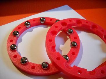
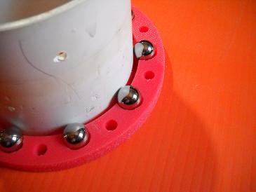
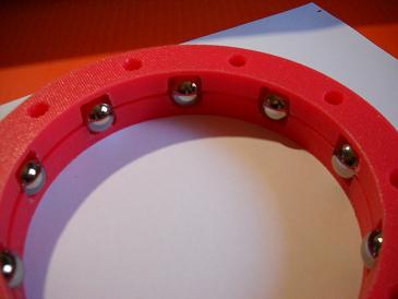
Hi, because I am increasing the blade length I have to install a blade support bearing. Fabrication was not difficult but I do not know how long it will last. Bearing ID is 4.26 inches and will fit beneath the PMA and ride on the PVC mast supporting the blade evenly during rotation. Comments welcomes. 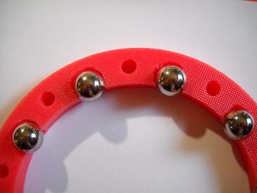
just because your a GURU or forum administer does not mean your always correct :) |
||||
| Rastus Guru Joined: 29/10/2010 Location: AustraliaPosts: 301 |
Hi Go Vertical, My preference would probably be metal caged with additional balls sharing the load.Just have to admire your "give it a go" attitude.Cheers Rastus see Rastus graduate advise generously |
||||
| govertical Guru Joined: 11/12/2008 Location: United StatesPosts: 383 |
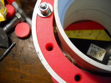
Hi, thanks for the suggestion. Can anyone recommend what type of grease to use? Adding more balls will be easy, it looks like two assemblies will be required. I can mount one on the top and bottom of the lower blade rotor and use a 4 inch coupler for a shaft collar. It does solve a lot of mechanical design issues. I can now evenly mount the 8 foot blades. It will be interest to see how long the plastic will holds up. I have been thinking I can make linier bearings for larger track slides to use with power tools, it opens up many possibilities. But one project at a time. 
just because your a GURU or forum administer does not mean your always correct :) |
||||
| govertical Guru Joined: 11/12/2008 Location: United StatesPosts: 383 |
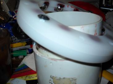
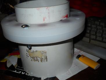
Hi, I purchased ¾ bearing balls and fabricated new bearing housing. I am using a 4 inch PVC coupler as a shaft collar. After I added some high temp grease the bearing spins freely and has a reduced noise signature. Spinning the assembly manually on the test fixture it is very stable and appears only one assembly will be needed for the lower blade rotor. The cost of a large ID bearing is over $500 US and at this time it appears to be a cost affective solution. 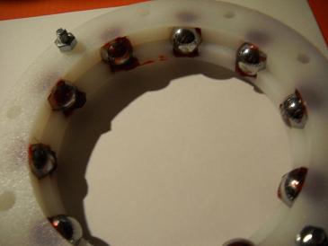
just because your a GURU or forum administer does not mean your always correct :) |
||||
| Tinker Guru Joined: 07/11/2007 Location: AustraliaPosts: 1904 |
A suggestion if what you made wears prematurely. I would try to have the balls adjacent to each other and not locked in a cage. This arrangement is seen in bicycles and runs very smoothly. Would be easier to make too, no precision dividing required. Regarding grease, water resistant trailer bearing grease should do fine. Klaus |
||||
| govertical Guru Joined: 11/12/2008 Location: United StatesPosts: 383 |
Hi, thank you for the suggestion, I will try it on the next modification. There is enough room to add 10 more balls and base on what I am observing with 10 balls when I 10 more plus your suggestion the unit should perform very well. Thanks again and enjoy the day.  just because your a GURU or forum administer does not mean your always correct :) |
||||
| Tinker Guru Joined: 07/11/2007 Location: AustraliaPosts: 1904 |
If you do go down that road you might consider to make an adjustable pre load for the balls. Simply let them run on a beveled surface and by changing the distance of the 2 halves (with shims) you can adjust the preload exactly without having to do super exact machining. Klaus |
||||
| govertical Guru Joined: 11/12/2008 Location: United StatesPosts: 383 |
Hi, thanks. Video link that shows the need for lower blade rotor assembly http://www.youtube.com/watch?v=o-GuG3u-450 Why the lower blade rotor is needed Once the lower blade rotor is installed below the PMA larger blades can be installed. When you consider the national wind speed average is 10 MPH, are you going to produce more current with a feather or a main sail? just because your a GURU or forum administer does not mean your always correct :) |
||||
| yahoo2 Guru Joined: 05/04/2011 Location: AustraliaPosts: 1166 |
Govertical, I would be interested to Know what type and grades of plastics you are using, I've had a look on the forums that I can find, where you are posting and I haven't seen it mentioned anywhere. I use a few grades mainly for lathing replacement bushes, just wondering how they compare to yours. I find one I use a bit soft, it deforms a lot if it gets warm or the clearances are not machined large enough. yahoo I'm confused, no wait... maybe I'm not... |
||||
| govertical Guru Joined: 11/12/2008 Location: United StatesPosts: 383 |
Completed lower mast blade rotor. Blade struts will be mounted with a U bolt and one ¼ bolts. I managed to make the ball housing so the balls do not fall out. 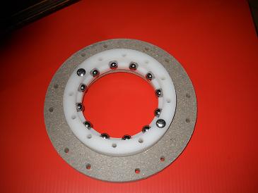
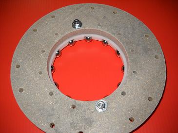
Hi, the gray material is a recycled plastic composite, all other plastics are HDPE. I use a light dimmer switch to control the CNC router speed. I slow the router speed and use a slow feed rate on the CNC when machining the plastic. The VAWT under load has a low RPM and all the plastic parts are working well for now. At some time in the future I would like to make a ebike to see if the plastic parts hold up. I completed the lower mast rotor and I am waiting for more parts to arrive so I can complete the new blades. Winter is here and the project may have to wait until spring, I am getting to old for the cold. 
just because your a GURU or forum administer does not mean your always correct :) |
||||