
|

|
Forum Index : Windmills : My smart drive wind genorator
| Author | Message | ||||
| fulfrog Newbie Joined: 20/01/2011 Location: New ZealandPosts: 13 |
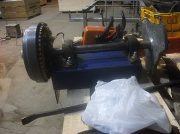
Hello guys iam new to this site and would just like to show you a windmill i am working on at the moment 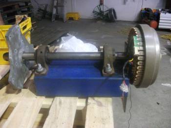
these are the blades i will be using 2.5m set 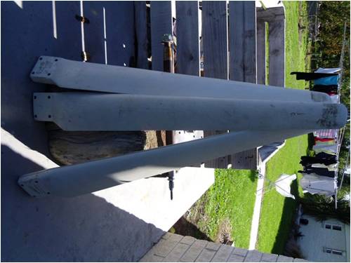
as you can see it is qwite big any help with mounting will be greatley apresheated Thankyou . Thanks Angus |
||||
| Gizmo Admin Group Joined: 05/06/2004 Location: AustraliaPosts: 5078 |
Hi Angus Looks good so far. Where did the blades come from, and what are they made of? Glenn The best time to plant a tree was twenty years ago, the second best time is right now. JAQ |
||||
| fulfrog Newbie Joined: 20/01/2011 Location: New ZealandPosts: 13 |
Hi Glenn i got the blades off http://www.ecoinnovation.co.nz im not to sure what they are made off but i think some sort of plastic Angus |
||||
mac46 Guru Joined: 07/02/2008 Location: United StatesPosts: 412 |
fulfrog, Is this going to be a down wind machine? or are you going to have the prop upwind and try to furl it with a tail? Also do you already have a tower, or one in mind...monting ideas might be easyer if we had more of this information. Thank you for posting you'e project, very interesting. ....Mac46 I'm just a farmer |
||||
| fulfrog Newbie Joined: 20/01/2011 Location: New ZealandPosts: 13 |
Hi all it's been awhile but I forgot I had it up here on the forum. Thought it was about time to continue to develop my design it's been sitting in the shed for nearly 2 years now. I mostly had the mill running and producing decent power. The problem with this was that it was a)very heavy and b) it had no safety in the design in the case of very high wind speeds, this wasn't much of a problem living on an orchard having easy access to a hydralada(cherry picker) but it soon became a pain. some photos bellow 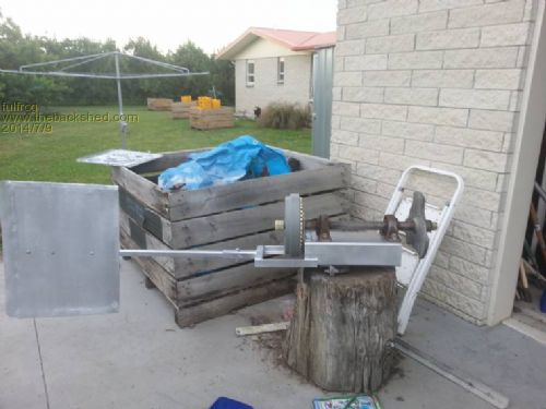
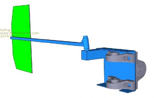
I am currently in the stages of building my second prototype this time lighter and with furling capability. I have done a little play on CAD to show a ruff idea of what I had in mind. I have started to create my mill to my cad drawings, I currently have the shaft at the local machinist getting shortened. Still thinking on how I will mount the stator open to help or ideas. 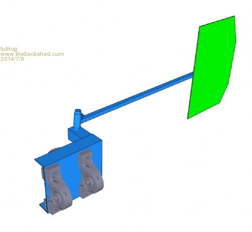
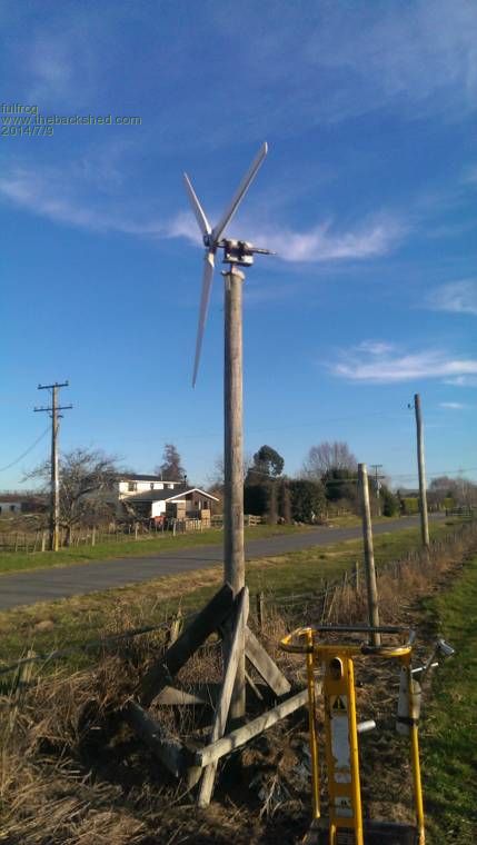
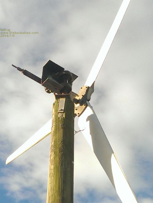
I still don't have an ideal tower but im planing on building/purchasing one in the future. When I get one, I will be changing the yaw bearings out for an option that will allow me to use slip rings. Cheers Angus |
||||
| kitestrings Senior Member Joined: 23/04/2014 Location: United StatesPosts: 102 |
Hi Angus, I think this looks really good. I like the idea of moving the alternator back and opposite the blades. It seems like a good way to distribute the weight and better manage the loads on the shaft. Chris Olson has several builds like this. I forget his website (Dairy something or other?), but you could google him on OP. The furling layout seems logical. Hard to tell from the photos what sizes are, but the tail looks a bit small to me. Hugh P. has a pretty good worksheet for calculating the torque and restoring moment. You'll need stops both top and bottom. Often the lower stop will be a bit past the 90 deg mark. I think ours is 100-105 degs IIRC. In lighter winds, where the tail boom stays pressed against the lower stop, this can help reduce the "skew" off the line of the wind. A couple more thoughts/first impressions: The yaw point takes a lot of slow speed thrust in addition to the radial loading. We used a bronze/composite thrust bearing. You might want to look at something - and it sounds heavy. Not sure how deep that pole is, but I wouldn't rely too much on those diagonal braces. Maybe some temporary guys? Hate to see your hard work come down in a unexpected high wind. Best of luck & keep us posted. ~kitestrings |
||||
| fulfrog Newbie Joined: 20/01/2011 Location: New ZealandPosts: 13 |
thanks kitestrings yeah ill look into some guy wires i was planing on using the current setup on the yaw for now and later i was thinking of switching it for a stub axel and hub with the tail it will be a bit of trial and error in reality. |
||||
| fulfrog Newbie Joined: 20/01/2011 Location: New ZealandPosts: 13 |
how strong is the stock 25mm f&p shaft anyone? i was considering getting a hub laser cut that fits on the 25mm shaft i notice allot of people out their use that setup. it just concerns me considering the size of the shaft on the hub that my blades came with. |
||||
Madness Guru Joined: 08/10/2011 Location: AustraliaPosts: 2498 |
Those shafts are very strong, I use spare ones I have for various things have given them a lot of abuse and never seen one bend of break. They are made to handle over 15 KG's of wet washing spinning out of balance at 1000 RPM. There are only 10 types of people in the world: those who understand binary, and those who don't. |
||||
| kitestrings Senior Member Joined: 23/04/2014 Location: United StatesPosts: 102 |
Yes, but while it is not exact science, there are some pretty good calculations and/or ROT that will get you very close, so it isn't all black art. On this site there is this: http://www.thebackshed.com/windmill/Docs/Furling.asp Hugh P has a really good basic formula (note the subsequent change he explains): http://www.fieldlines.com/index.php/topic,146065.msg997497.h tml#msg997497 Hope this helps. ~kitestrings |
||||
fillm Guru Joined: 10/02/2007 Location: AustraliaPosts: 730 |
Yes they can handle a lot of abuse but in the F&P Washing Machine the out of balance sensors stop the spin cycle long before it gets to out of control and dancing all over the laundry floor . I have only seen one bent shaft, and the mill 3.2m Dia would have been doing 1000+ Rpm in over 130klm of wind when a blade contacted a guy wire and ripped it of , whether it was the initial impact or the mill then completly destroying its self there after, the shaft then measured .4mm run out. KiteStrings I have used the " Add HyperLink " . It gives easy access to your links, you can just click on them now .... makes it easy. http://www.thebackshed.com/windmill/Docs/Furling.asp http://www.fieldlines.com/index.php/topic,146065.msg997497.h tml#msg997497 As for formulas to work out furl moment, its not worth the trouble and head scratching as there are to many variables ,as Hugh says ( But that formula should be close with the sort of blades that I make and describe.) Different blades / different tails , weights and on and on - how can any one formular give an answer . In my experience is people read what is in the formular and then just use the example and go with-(So for our windmill to start furling at 72kmh, it needs a tail pivot angle of 20deg, a tail lenght of 1.378m and weight of 20kg.) 20kg tail weight with 20deg lay back which is a ridiculous figure for a 2m Dia Mill, then to go off and think this is a good starting point. My advice to you is to experiment and try this as a start point , 80~100mm blade offset , make a tail light and long ( minimum being the blade radius ) the tail pivot is then 3~5deg laid back and then experiment with the side angle ( start at 12 ~ 15deg). By either just changing the side angle or adding and subtracting tail weight will increase or decrease furling . Also Give the tail 10 ~ 15deg angle to the opposite side of blade offset to counteract the blade offset force. *The Out-clause ( this is what I have found that works best with the GOE222 blades I use) The other option here , the F&P will never burn out no matter how hard and fast it runs .... just build it like a brick sh!thouse , balance it perfect and just let it go , they run at 1000 + in hydros all day 24/7.  PhillM ...Oz Wind Engineering..Wind Turbine Kits 500W - 5000W ~ F&P Dual Kits ~ GOE222Blades- Voltage Control Parts ------- Tower kits |
||||
| kitestrings Senior Member Joined: 23/04/2014 Location: United StatesPosts: 102 |
Hi Phil, I tried the hyperlink icon to no avail. All the others work (quotes italics, etc), but when I hit this one nothing happens at all. I'm on a laptop with Windows8. Can't say it is that, but certainly had some new challenges with it. Admin(s), if you have a suggestion, please let me know. I think we perhaps have the same underlying message. There are a number of rules of thumb put forth by folks like yourself who've been at this awhile. Even a range on things like off-set, boom length, vane size, angles... to me it's a better place to start from (rather than us all repeating the same mistakes). And most of these can be found here and elsewhere, where wind-nuts flock. I'm not at all familiar with Angus' blades are they similar to the GOE222's? kind regards, ~ks |
||||
Downwind Guru Joined: 09/09/2009 Location: AustraliaPosts: 2333 |
With some systems once you click the Hyper link button you will see a yellow bar to the top of screen asking for permittion to run this app, click the yellow bar, then retry the hyper link button, this time it should work. Pete. Sometimes it just works |
||||
| kitestrings Senior Member Joined: 23/04/2014 Location: United StatesPosts: 102 |
Pete, Doesn't seem to work here. I've tried it recently on another forum; worked fine. It seems to be unique to my connection here. Sorry for the diversion Angus. ~ks |
||||
| fulfrog Newbie Joined: 20/01/2011 Location: New ZealandPosts: 13 |
Thanks so much for your help Phill. I am unsure if the tail pivot point is offset aswell, or is it in-line with the Yaw point, i couldn't really find a clear answer for that on those links?. Your right the smart drive will never burn out so ill continue to build it strong (well attempt too). Cheers. |
||||
| domwild Guru Joined: 16/12/2005 Location: AustraliaPosts: 873 |
If the blades are plastic and I have not read all the replies, then get a liquid primer from Bunnings, which sticks to plastic, then paint it white as UV is your enemy. Good luck! Taxation as a means of achieving prosperity is like a man standing inside a bucket trying to lift himself up. Winston Churchill |
||||
| fulfrog Newbie Joined: 20/01/2011 Location: New ZealandPosts: 13 |
there fibreglass with a plastic type finish by the looks of it. |
||||
| fulfrog Newbie Joined: 20/01/2011 Location: New ZealandPosts: 13 |
Did some work on the windmill this weekend hopefully will be able to so some more this weekend. 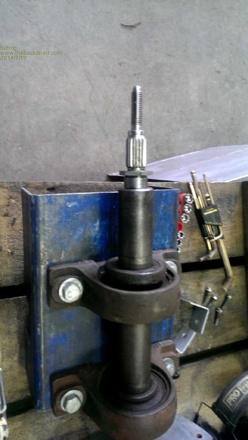
I have got my shaft back 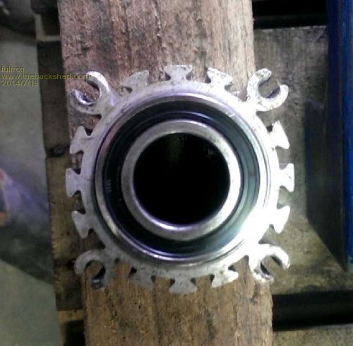
I have melted the plastic of the stock bearing housing and have shortened it so that it only has the bearing at the stator mounting end 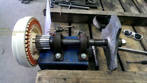
starting to get somewhere :) am unsure if the tail pivot point is offset aswell, or is it in-line with the Yaw point? can someone help with this? |
||||
fillm Guru Joined: 10/02/2007 Location: AustraliaPosts: 730 |
You can off-set if you want, some say you should have it the same distance as your blade off-set .... give that a go ,or whatever you can get to work best with your design. PhillM ...Oz Wind Engineering..Wind Turbine Kits 500W - 5000W ~ F&P Dual Kits ~ GOE222Blades- Voltage Control Parts ------- Tower kits |
||||