
|

|
Forum Index : Windmills : Tim’s Windmill
| Author | Message | ||||
Tim_the_bloke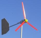 Senior Member Joined: 15/11/2009 Location: AustraliaPosts: 105 |
I want to share details of my current windmill. I was given this Chinese made windmill as incomplete parts with a few extra few non matching bits. I think it is meant to be a 500W model as from Jaycar, because it has sliprings and looks like their 500W model. I have carefully looked at the images Jaycar/Electus use in their advertising and reckon it is not an exact match. However, I suspect that each batch from China is a different design. 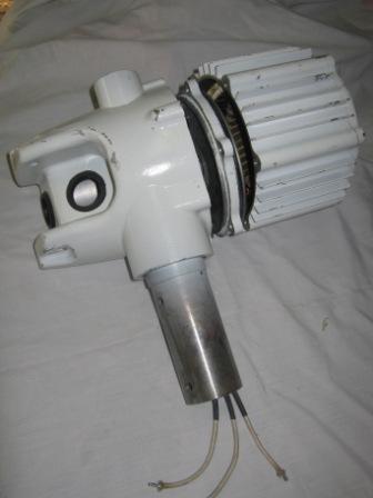
Being typical Chinese manufacture, the design is better than I can do but the metal work is very disappointing. I pulled it apart to see what was inside and in putting it back together found the long steel bolts holding it together strip the thread in the alloy casing. So, I drilled out the threaded holes in the casing for longer bolts. I could not source longer bolts to buy so I made some by welding nuts onto threaded rod. 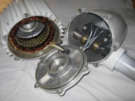
I cleaned the contacts on the slip ring setup as they were very tarnised. 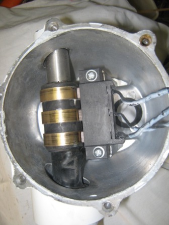
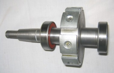
I removed the bearings and bought Japanese replacements which I then installed. 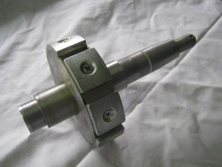
The stator has tapered windings which I think (hope) is designed to reduce cogging. 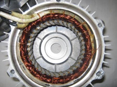
The tail is made from 3 peices of square section steel (35mm from memory) welded together and a sheet of plywood. A piece of rubber from an old thong for a cushion to the stop, a strong bolt, washers and cotter pin for the pivot. The blades are from an earlier different Chinese windmill (Jaycar's 1st model). I cut the blades shorter to remove the section with bolt holes as the holes were in the wrong spaces, and drilled new holes to suit the mounting plate which fitted the rotor shaft. The blades are still approx 800mm long. The blades have also been tapered, shaped, sanded and had a spoiler added as advised on The Back Shed. The spoiler indeed does greatly reduce blade noise. 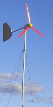
This windmill has now been operating for almost a year (as of may 2011) and is working. It has suffered slight damage to the blades in that the whipper snipper cord spoiler started coming off towards the end of a blade. I snipped off the loose few inches. This may unbalance the blades a little, but it still seems OK. Electrical perfomance wise I am somewhat disappointed in that it normally pushes only 1.5A into the 12V battery bank, so nothing like 500W. Mechanical performance wise I am pleased it is still spinning and upright and creating current. |
||||
mac46 Guru Joined: 07/02/2008 Location: United StatesPosts: 412 |
Tim_the_Bloke, A few things come to my mind... it may not be reaching high enough rpm to achive cutin, however I don't think this is the problem, You did'nt say, - Is the stator and rotor a matched set? It looks like a "Fine machine", great project. Other's may want to chime in to help you with troubleshooting procedures. But I think I would start with pulling it down off the tower and mounting it on a test stand so you can take readings under controled conditions and pinpoint the problem, or problems. .....Mac46 I'm just a farmer |
||||
| VK4AYQ Guru Joined: 02/12/2009 Location: AustraliaPosts: 2539 |
Hi Tim I think your machine is the 200 watt version as I have a 500 watt one and the stator and magnets are a lot bigger than yours appear to be in the photos. They need to run very fast to generate useful amounts of power and the original blades do not perform well at all. I have tried a few high speed blades on mine, and have gone to a 2.5 meter high speed set , but it takes wind over 10 ms to get going well a 12 amp at 30 volt output but by 15/18 ms it goes to 30 amps. In over 20 ms I have seen it peg out the 50 amp meter. I have no furling on mine as it needs to go fast. The original furling wasn't worth a pie anyway. I believe they are rated at 12.5 ms and from what I have seen on mine they need better blades to do their correct output. Yours is the later version than mine as mine has no slip rings, but is very robust in construction. Are you using the original regulator? if so teach it to fly and put a good 3 phase rectifier on it as the original ones are a heap of rubbish. All the best Bob Foolin Around |
||||
| Gizmo Admin Group Joined: 05/06/2004 Location: AustraliaPosts: 5078 |
Hi Tim Nice post. Can't help much with the low output, other than it does seam too low, but it depends on the wind your getting too. Yeah, that blade mod makes a lot of difference to the noise, and you get a little more power as a bonus. I would convert it to studs. Instead of welding a nut onto a length of allthread to make a longer bolt, screw and locktight lengths of allthread into the original re-tapped threads, and then use nuts to secure it together. Since you will never be removing the allthread ( studs ), the aluminium thread will last longer. Its something a mechanic taught me, when a steel bolt strips a aluminium thread in a engine part, throw away the bolt and use a stud instead. Glenn The best time to plant a tree was twenty years ago, the second best time is right now. JAQ |
||||
Tim_the_bloke Senior Member Joined: 15/11/2009 Location: AustraliaPosts: 105 |
Mmm, that does sound better, but it is all done now. Next time I will think of that. |
||||
Tim_the_bloke Senior Member Joined: 15/11/2009 Location: AustraliaPosts: 105 |
Yes, the stator and rotor came together and took some disassembling. Once apart the bolts would not go back together, which is why I had to make up new long bolts. |
||||
Tim_the_bloke Senior Member Joined: 15/11/2009 Location: AustraliaPosts: 105 |
No. Yes the rectifier they come with are rubbish. However, this one did not come with one. I used my earlier rectifier charger which has gone through several modifications but is based upon the Oatley Electronics kit, with a dummy load and extra meters. |
||||