| Author |
Message |
kevindion
Regular Member

Joined: 28/07/2010
Location: ChinaPosts: 59 |
| Posted: 04:44am 04 Jan 2011 |
 Copy link to clipboard Copy link to clipboard |
 Print this post |
|
english is not my first language,so i hope you guys can understand my terrible english skill.
first,i used iron to make rotor,it is easy get flexed,and that is what happen on my rotor,i should used steel.
my turbine was 8 magnets on each side,and i mount 3 magnets together for making more magnetic field,so in reality there were 16*3=84 magnets on my rotor,but i got a low result when i test the"hand coils".
It made 0.3v£¬0.18A at 180rpm,with 20turns for one coil.Does it mean i get make 200turns per coil so that i can get >12 volts to charge my bettery bank?or i could just used thinner wire? my magnets were from bike moto,was it the problem? |
| |
VK4AYQ
Guru

Joined: 02/12/2009
Location: AustraliaPosts: 2539 |
| Posted: 05:38am 04 Jan 2011 |
 Copy link to clipboard Copy link to clipboard |
 Print this post |
|
Hi kevin
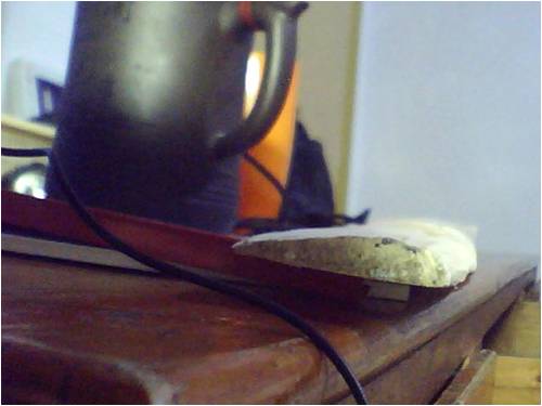
Looking at the photo you posted the magnets where curved, that resulted in a larger air gap to the coil, the magnets should be flat to get the most flux through the coil.
The more flux the higher the volts and amps.
See if you can get some flat magnets to try, and set your air gap to .5mm maximum to get a more realistic reading.
All the best
Bob
Foolin Around |
| |
Downwind

Guru

Joined: 09/09/2009
Location: AustraliaPosts: 2333 |
| Posted: 05:46am 04 Jan 2011 |
 Copy link to clipboard Copy link to clipboard |
 Print this post |
|
Your English is fine we can understand.
Think you have several problems, and weak magnets are a main cause.
Power out is equal to magnet strength.
The stronger the magnets the greater the power.
The thickness of the steel plates will also effect the power and thin iron as you used will give less power.
The air gap between magnets and coils will effect results with a wider gap you will get less power.
The shape of the coils to the shape of the magnets will effect the power output.
The number of magnets around the disc will effect the power.
The spacing between the magnets will effect the power.
Thinner wire will not increase voltage only reduce the amps.
The bigger the wire the more amps you can make.
The voltage is increased with the more turns you have per coil.
As you can see there is many things that could effect how well your generator works.
Pete.
Sometimes it just works |
| |
kevindion
Regular Member

Joined: 28/07/2010
Location: ChinaPosts: 59 |
| Posted: 06:56am 04 Jan 2011 |
 Copy link to clipboard Copy link to clipboard |
 Print this post |
|
Thanks a lot.
There are some details on my turbine..

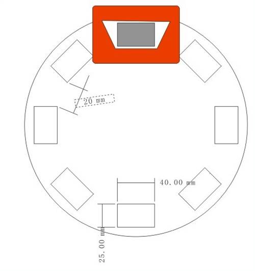
As you see,the magnet is 40*25*15(i put 3 magnets together,it was 40*25*5).
The shape of my coils was trapezoid,and there is 20mm between magnets' leg,my coil's leg is the same wide as the air gap between magnets,i thank that should be a rule during wind my coils,is it? it was 0.5mm between coils and magnets.
Downwind is right about my problem.The magnet is too week.,even i put 3megnet together still cann't make them stronger.(But they are strong enough to break my fingers!!).
For imrpove my turbine,by following your advises,i will make some changes.
First, I will change my iron rator to be steel rotor.
Second, i will consider to buy some flat magnets.
VK4AYQ,what is "set your air gap to 5mm"? it is the air gap between magnets or magnet-coil-megnet?
It is more difficult than i thought to make wind turbine,i realy make a lot of mistakes,the only good story is i figue out how the alux flux windmill works!so everything would going well!
Thanks a lot!You guy are very nice!!
I am not interested in any business,but i have some strong relates in China include the area of Inport%Export,so if you have any quetion about china,just tell me that you are the member from this fourm,i will always be there for you.  |
| |
VK4AYQ
Guru

Joined: 02/12/2009
Location: AustraliaPosts: 2539 |
| Posted: 08:36am 04 Jan 2011 |
 Copy link to clipboard Copy link to clipboard |
 Print this post |
|
Hi Kevin
It is a steep learning curve
the air gap to the magnet face from the coil should be a half a millimeter 1/2 mm each side of the coil. As Pete said a good heavy steel plate for the magnet mounts will be much better.
Thank you for your kind offer also.
All the best
Bob
Foolin Around |
| |
Downwind

Guru

Joined: 09/09/2009
Location: AustraliaPosts: 2333 |
| Posted: 10:44am 04 Jan 2011 |
 Copy link to clipboard Copy link to clipboard |
 Print this post |
|
Ok you have given some good data to work from. 
For best results you should have 12 magnets a side not 8 as you have.
The best coil shape would be if you cut a block to wind your coils around the same size and shape as the magnets, so it was close to the same internal hole size as the magnets outer size.
The coils need to be placed in the stator so every magnet will line up close to perfect with the hole in the centre of the coil as it passes the over the coil.
The magnets also needs to align close to perfect over the coils that are all connected in series with one another spaced around the circle (ie 3 lots of 3 coils )
This means very good alignment of the magnets and good placement of the coils is very important.
I would aim for a 1mm air gap between the magnet face and the coil with the option of closing the gap to 0.5mm as Bob surgests after you have it all working well.
The air gap refers to the gap between the magnet face and the coil outer surface.
So you should be able to slip a 1mm sheet of cardboard between the magnet and coil, for a 1mm air gap as we call it.
This applies to both sides of the coil/stator and a 1mm air gap is required on both sides between the magnets and stator (coils)
Pete.
Sometimes it just works |
| |
kevindion
Regular Member

Joined: 28/07/2010
Location: ChinaPosts: 59 |
| Posted: 11:43am 04 Jan 2011 |
 Copy link to clipboard Copy link to clipboard |
 Print this post |
|
i take your points,but my quetion is can i use car or bike magnets to make windturbine? This magnets are on N38 grade, I think they are viable,but i failed and didn't even closed to the end of this project.
There is guy in this fourm,in his post,he show a similar project like my turibine,i hope he can done his windmill at future,we will see.I will buy some flat magnets,im sure it could save a lot problem.
Thanks,men. |
| |
kevindion
Regular Member

Joined: 28/07/2010
Location: ChinaPosts: 59 |
| Posted: 10:21am 05 Jan 2011 |
 Copy link to clipboard Copy link to clipboard |
 Print this post |
|
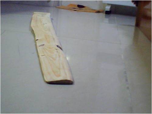
this is the blades i made.It is suck!

i gut this wood from a fresh wood,and it have a lot of knots on the front area.but i still will done with this blades,at least i can have a toy.
it is a good arefoil shape?

Edited by kevindion 2011-01-06 |
| |
Tinker

Guru

Joined: 07/11/2007
Location: AustraliaPosts: 1904 |
| Posted: 01:08pm 05 Jan 2011 |
 Copy link to clipboard Copy link to clipboard |
 Print this post |
|
Its OK to practice making blades from poor quality wood but for serious long time use you need to source much better quality wood.
If you can't find wide knot free pieces you can glue several good quality narrow strips together to make up the blade blank. This is called 'laminating' and the ideal glue to use for that is epoxy resin. The type boat builders use.
While I have not yet made windmill blades this way I do have experience laminating rudder blades for sailboats. These are very strong and light which is also important for windmill blades.
I have seen several articles on how to shape wooden blades for a windmill on the net, I'm sure if you follow the instructions you get a good blade profile.
Klaus |
| |

