|

|
Forum Index : Windmills : Another way to reduce cogging?
| Author | Message | ||||
| Gizmo Admin Group Joined: 05/06/2004 Location: AustraliaPosts: 5078 |
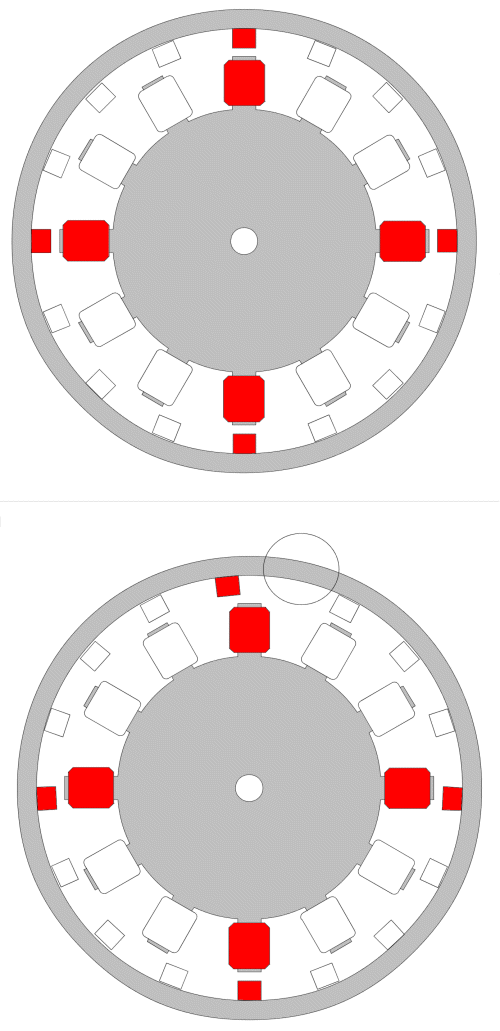
I've been thinking about this for a while, a way to decog a F&P. I spoke to Michael of EcoInn a couple of years ago and he mentioned the latest F&P motors dont have any cogging, and he said there was something a little "different" about the magnet spacing in the hub. And then I noticed someone pulled a AirX windmill apart and posted the pictures on Fieldlines. Then the little light bulb above my head started flashing. First up I suggest you read the articles on Filedlines, just click on the links below. http://www.fieldlines.com/story/2006/6/28/5533/81710 http://www.fieldlines.com/story/2006/6/30/6232/91427 Now to the theory. This is hard to explain, but hopefully with the pictures you can see what I'm getting at. The first picture below (sorry they are so big, but I needed the detail) shows a 12 pole 16 magnet 3 phase alternator, typical design. Stator in the middle, magnet rotate around the out side, magnets at 22.5 degrees apart. I've coloured one phase red. You can see there are 4 magnets lined up exactly with 4 stator poles. This would make the alternator hard to get started ( cogging as we call it ). Now look at the 2nd drawing. The magnets are slightly offset. There are still 16 magnets, but they dont quite make it around and are spaced at about 21.5 degrees apart, leaving a gap ( circled ). This gap is only a few degrees wide. This means there will never be more than 1 magnet aligned with a pole, the other magnets for that phase are close, but not exactly lined up, they are spread out a little. And the magnets for the other phases are also spread out a little. See where this is going? There is no peak in magnet flus as the magnets pass the stator poles, more of a gentle hump. With the correct magnet spacing, the gentle humps for each phase will join to give a near smooth rotation, no cogging as we know it. 
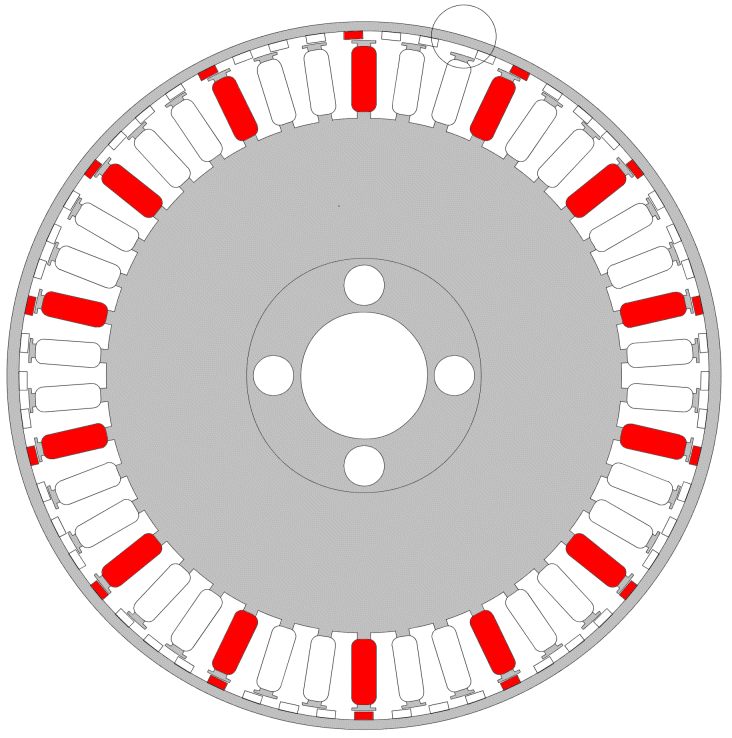
There would be a small loss in output voltage, as the flux peak on all poles at once is missing, but there would also be a increase in current. The sine wave would have a flatter peak, but wider mid rage where the real power is, around the RMS level. I see a lot of induction motor conversions with evenly spaced magnets, but I believe a uneven spacing would reduce cogging, instead of skewed magnets or laminations. Now for the grand finally. F&P. For the Neo conversion guys. I drew up this drawing... 
Each magnet is installed slightly under the 6.428 degrees spacing they are from factory, closer to 6.39 degrees will give a "gap", shown circled. You can see how only one magnet and stator pole is exactly aligned for the highlighted phase, reducing the cogging effort by 14 times!. There would be a slight reduction in peak sinewave voltage, but a slight increase in current, and with so many poles, virtually no cogging, even with neo magnets. But this is theory, I havn't tried it and may be missing something. But I do know the AirX windmills use uneven magnet spacing. Please let me know what you think. A F&P with Neo magnets and no cogging would be a awesome beast. 
Glenn The best time to plant a tree was twenty years ago, the second best time is right now. JAQ |
||||
| Gizmo Admin Group Joined: 05/06/2004 Location: AustraliaPosts: 5078 |
Just a note, I havn't done the math yet, so the angles I've stated are approx. Will work out the exact angles for a F&P tomorrow, brain too tired today. 
This is where a plywood template would come in handy to align magnets while gluing into place. The angles would have to be spot on. If this idea would work, I'll look into laser cutting a bunch of templates for those that want to give it a try with neo conversions. Glenn The best time to plant a tree was twenty years ago, the second best time is right now. JAQ |
||||
| brucedownunder2 Guru Joined: 14/09/2005 Location: AustraliaPosts: 1548 |
Well done ,Glenn. I've been "internet down" for a day so Trevor might like to try again with my questions? I'd like to glue some Neo's in a F&P rotor that I have stripped for this purpose- bye the way the magnets come out fairly clean and easy ,after the first one. Enclosing a pic of a F&P rotor that Matt from melbourne did when he visited my place. If Glenns idea works ,I'll recover these Neo's and try for a dual set. hahaha,just joking. Bruce  Bushboy |
||||
| Gizmo Admin Group Joined: 05/06/2004 Location: AustraliaPosts: 5078 |
The angle I've come up with is 6.3920 degrees between magnets. This leaves a "gap" of 8.44 degrees. The default angle from factory is 6.4285 degrees. It took a lot of coffee to work this out, and I'm not 100% sure its correct. The idea is to spread the magnets over the poles of one phase, without crossing over to the next phase. So for the 14 poles of each phase, each magnet is slightly offset. So as the hub rotates, each of the 14 magents pass the same phase pole in sequence instead of at one time. But you need to make sure the magnets for the next phase dont start their sequence until this phase is done. I've attached a zipped up DXF file, for anyone with a CAD program. This is still theory, but I think it works. Glenn 2006-07-16_111112_decog-fp.zip The best time to plant a tree was twenty years ago, the second best time is right now. JAQ |
||||
| Highlander Senior Member Joined: 03/10/2006 Location: AustraliaPosts: 266 |
G'day fellas, if airx use this it must be pretty good. Those little buggers spin like a top in a slight breeze. How about we adapt it to the F&P perhaps 7 or 14 phase? Central Victorian highlands |
||||
| brucedownunder2 Guru Joined: 14/09/2005 Location: AustraliaPosts: 1548 |
Hello Highlander and Glenn., I've got the new rotor up (factory-non cogging), and it spins up much quicker than any of our home-made neo types or the old Ceramic rotors from the factory. Good. But I've a feeling we're not going to get anywhere near the power from the new rotor that is apparently available from my Neo conversion. (On the weekend the new rotor was really powering along and all I could see from it was 225 watts. Whereas if I remember right ,the neo conversion gave out close to 800 watts or more a few times in a big blow. So, I'd like to keep on with the experiment with the small neo's in the hope that maybe we can get a breakthrough. Bruce Bushboy |
||||
| Megawatt Man Senior Member Joined: 03/05/2006 Location: AustraliaPosts: 119 |
Very intersting brucedownunder2. Also a bit exciting for me. If you look at the saturation thread, you'll see that I am pretty interested in detrmining just how much magnetic flux will saturate a F&P pole. This is because after saturation you get no improvement in performance with further attempts to increase magnatisation, while you can have reductions because of waveform disturbance etc. I have been wondering whether neos can provide too much flux, so saturating the cores. Your report indicates that more flux that is available from the new rotors is of value to achieving greater power output, always assuming the air gap is the same. One possible counter to this argument is that Mr F&P has an interest in continually upgrading the performance of his machines while reducing their cost. There's an American report about the latest Smartdrive motors only using 200 watts - they would not need such strong magnets. If so, it could explain the reduction in output. We'll see - I'm really looking forward to test results by an enthusiast. Megawatt Man |
||||
| Highlander Senior Member Joined: 03/10/2006 Location: AustraliaPosts: 266 |
Hey Glenn, I know your busy but if you get a chance can you work out the spacing with a gap for the 7 phase. You won't be wasting your time. I WILL DEFINATELY TRY IT. I don't need a cad or drawing just the mm gap size, I can do the rest. Sorry I'm not mathematically inclined to work it out myself. Bruce your magnets look like a good size and shape to do an arrowhead shape similar to the new FP magnets, just a thought. Central Victorian highlands |
||||
| Megawatt Man Senior Member Joined: 03/05/2006 Location: AustraliaPosts: 119 |
Highlander, don't be sorry, you're a goer mate. Yes, go the arrow head arrangement, it will reduce cogging. Megawatt Man |
||||
| brucedownunder2 Guru Joined: 14/09/2005 Location: AustraliaPosts: 1548 |
Yes Guys, I would like someone to try an replicate the latest F&P rotor. If you are stuck for magnets,Matt Lyons in Melbourne,down Avalon way now, I think(hey Matt, get in touch with us ,we miss You!!) has a stack of small magnets that will do the job-I say these because you can arrange these in an arrow fashion like the new F&P rotor. I tried taking the thin strip magnets off an old rotor , but they are fixed very firmly and won't budge. Bruce Bushboy |
||||
| Highlander Senior Member Joined: 03/10/2006 Location: AustraliaPosts: 266 |
Hey Bruce did you try a bit of heat? It will stuff the rotor and not sure of the effect on the magnets but enough heat should melt the glue/resin. Central Victorian highlands |
||||
| brucedownunder2 Guru Joined: 14/09/2005 Location: AustraliaPosts: 1548 |
Tried to remove those little strip magnets that F&P put in their original rotor(very scarce to get now)-no luck-- Every one breaks into lots of pieces, they might be Neo's , but they are very thin and have no strength when prising them out. We had a storm last night ,so dressing gown on ,I went to the control panel to see the peak watts-350 watts- ,this is with the new F&P rotor and re-configured 7/2 .8mm stator. Soooo, not so good ,compared to the cogging Neo conversion rotor and 3 /2 stator, which gave out in a similar storm nearly 800 watts. But I'll keep experimenting-welding up a new direct drive mill platform today. Bruce Bushboy |
||||
| Highlander Senior Member Joined: 03/10/2006 Location: AustraliaPosts: 266 |
Alright Glenn I'm out of experiments. How about we give this a go wit the 7 phase? I was thinking if you look at your cad and measure the gap for the 3 phase then divide it by the no of magnets and multiply that by the number of 7 phase magnets it should work out the same  Central Victorian highlands |
||||
Gill Senior Member Joined: 11/11/2006 Location: AustraliaPosts: 669 |
Gismo, how about instead of offsetting the magnets, within the range of perceding and following magnets, that we grind progressive lead in and lead out bevils off the iron core. A refined version of our old decogging practice of rounding off the tops of the cores? Further to this I would randomly position these modified crowns of each phase around stator to elimimate drummimg vibration and not as the explanitory sketch indicates. was working fine... til the smoke got out. Cheers Gill _Cairns, FNQ |
||||