|

|
Forum Index : Windmills : Physical/Hydraulic/Electromechanical Braking of Turbines?
| Author | Message | ||||
| Kamak Senior Member Joined: 13/04/2021 Location: CanadaPosts: 150 |
The Neotard Retarder |
||||
| kitestrings Senior Member Joined: 23/04/2014 Location: United StatesPosts: 102 |
Yes, isn't this similar to what they use on those mag-lev trains? It is an interesting approach. I recall the company I worked for, Enertech it was called, had a dynamic brake design on a fairly large turbine... ~40 kW IIRC. They used water immersion elements in free air, but they were only good for the one, fail-safe attempt and then had to cool. We use a combination of strategies for speed-control and self-protection. Initially, keep the thing electrically loaded, right, so charge the batteries in our case. Then we load-divert to a pre-heat tank for hot water. We also have a resistive load-bank on the 3-ph source that is triggered off a PWM relay setting on the CC. It is a user-adjustable V-hi setting. So when the batteries are charged and the water is hot, this provides load. On the mechanical side, there is the furling. A big gust and the turbine folds presenting a smaller and smaller ellipse to the wind. You give up some of the high-wind potential, but in the end it is very soft, passive and forgiving. This operates independent of the actuator, solely based on thrust on the rotor versus restoring moment. Lastly, on another non-PW relay setting, we have a (NC) contact that will open when a bit higher voltage is reached and furl the turbine with the actuator. My admitted bias is to have things as simple as possible up on the tower, and keep the electronic wizardry on the ground; inside if possible. |
||||
| Kamak Senior Member Joined: 13/04/2021 Location: CanadaPosts: 150 |
I agree with you on simple, and robust, and as little electronics up on the tower, as possible. But if a permanent Neo magnet eddy current disc could be used, that's dead simple. The cool thing about eddy current brakes is that they are self-adjusting, to a certain degree, without a single external control added. The faster the disc moves through the magnetic flux, the more drag is created. So that gives a certain inherent degree of proportional applied torque resistance. Only as the torque surpasses the applied flux field's ability to maintain a steady rotational speed, would a magnetic proximity adjustment need to be made. But that's also very simple to implement. The electromagnet makes this even simpler, but it's bulkier and with less magnetic flux density per volume. But it might be the best way. |
||||
| Kamak Senior Member Joined: 13/04/2021 Location: CanadaPosts: 150 |
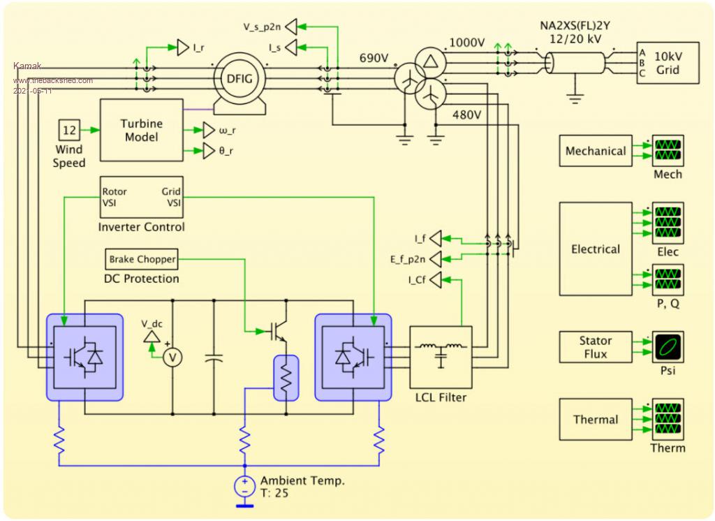
Understandably, the other method of speed control is load control, using torque. This is how some of the big boys do it. It's called a doubly-fed induction generator converter (DFIG). This demo of a modeler called Plexim describes how it works, and allows a free trial for a month, with access to the files that model this wind turbine system. I might check it out just for educational fun. https://www.plexim.com/sites/default/files/plecs_dfig.pdf https://www.plexim.com/support/application-examples/282 |
||||
| pollenface Regular Member Joined: 01/09/2020 Location: AustraliaPosts: 47 |
I have a 24v system and a cheap 3-phase 24v turbine. I rigged up a brake using 2x automotive relays which short the 3-phases on the AC side of the rectifier using a voltage sensing relay from a dual battery system. At 27.4v the VSR supplies signal to the 2x automotive relays and it brakes the turbine. At 25.6v it recovers. My 1kw solar array virtually makes this system redundant during good sunlight hours as my mppts float @ 27.6v, thus my turbine is only functional during non-sunlight hours or rainy days and under wind power alone it doesn't get anywhere near the braking voltage. My system works well with the small turbine, but I am unsure as to how well it would work with a larger turbine with more (spinning) inertia. On another note... I hypothesized building a turbine with a centrifugal clutch from a whippersnipper and adjusting the throw of the clutch pads to engage at high rpm (eg hurricane wind). Edited 2021-05-11 09:50 by pollenface Off grid man caver |
||||
| Kamak Senior Member Joined: 13/04/2021 Location: CanadaPosts: 150 |
Yup. those are all really great ideas, I hope you can demo the weedwhacker idea, here someday. I am also itching for an approach that will allow charging and speed control simultaneously and something that is frictionless, in doing so. Something like a simplified DFIG idea (if that is even possibly simplifiable) or a truly simple frictionless eddy current brake/torque reactor. Also something along the lines of a "parking brake". Something manual, that once the rotor is slowed down to a stop, then locks it in place. A smallish motorcycle brake could possibly do, without adding too much mass, I suppose. |
||||
| Kamak Senior Member Joined: 13/04/2021 Location: CanadaPosts: 150 |
This is how some of the big boys do it. It's called a doubly-fed induction generator converter (DFIG).  |
||||