| |
  Page 12 of 12 Page 12 of 12 |
| Author |
Message |
KarlJ

Guru

Joined: 19/05/2008
Location: AustraliaPosts: 1178 |
| Posted: 08:34am 11 Mar 2010 |
 Copy link to clipboard Copy link to clipboard |
 Print this post |
|
all sounds complicated Gordon, do you do it just because you can?
I've read your posts on MPPT before and it looks like a loosing game, may be why there aren't too many on the market.
What kind of improvement do you expect over the CAPS,
you're currently running a doubler, tripler and quadradoobler yes?
Good luck BTW, we continue reading with great interest.
Cheers Karl
Luck favours the well prepared |
| |
GWatPE

Senior Member

Joined: 01/09/2006
Location: AustraliaPosts: 2127 |
| Posted: 08:02am 12 Mar 2010 |
 Copy link to clipboard Copy link to clipboard |
 Print this post |
|
Hi Karl,
MPPT is still the holy grail for a windmill. I suppose I have a personal quest. As for doing it because I can, maybe true.
I have a philosophy for any windmill, if it is turning, that it should produce power.
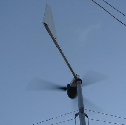
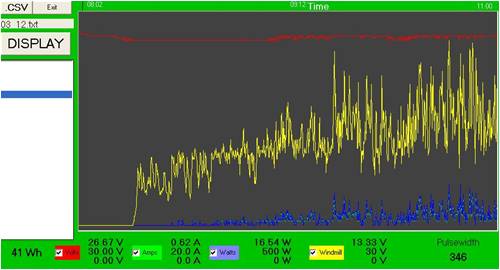
Here is a graph of a 3 hour period of my windmill, just starting up in very light winds. This would not have produced any amps, without a boost cct. This happened to be my new MPPT. This windmill is a 4phase output, with rectifiers on the mill head, and DC down the pole. This was not a candidate for Caps, so an electronic boost it had to be.

Cutin starts at around 100rpm, 8VDC OC, in around 1m/s winds. Probably <1W available. The windmill only put 41Wh back to the battery in this time.
In areas that only get low winds, the windmill can spend a lot of time like this. Even at 40Wh for 3 hours can amount to 0.3kWh over a whole day. This is better than nothing at all, that could have been the case, in the same winds, without a boost mechanism.
I do not expect improvement over a capacitor boost arrangement in the same small scale application, but I see an electronic form having a more universal application, and extending to larger scale systems..
I am experimenting to conclude my unsatisfactory results a few years ago with a micro controller.
I don't think MPPT is a losing game, as a better result is obtained. If the 80/20 rule applies, there is a lot of the day, that a boost will help. The wind energy spectrum dictates how much can be obtained from this 80%.
Gordon.
BTW my 3phase AxFx mill still has the caps.
become more energy aware |
| |
GWatPE

Senior Member

Joined: 01/09/2006
Location: AustraliaPosts: 2127 |
| Posted: 02:13pm 11 Apr 2010 |
 Copy link to clipboard Copy link to clipboard |
 Print this post |
|
Well, parts of my old F&P alternator are flying again. There is no F&P left now. I reused the outer rotor, blade mount and trailer stub axle/tapered bearings hub. I had a new rear magnet plate, and stator adapters laser cut.
The new stator works well, and in 10-15knot winds this afternoon, the unit has produced just over 1kWh, with a peak of 510W. I have retained a cap doubler, but the series caps are not needed. Cut in is about 110RPM.
I now have 2 similar units, with similar magnets, and internal geometry. These are fully interchangeable on my towers. I should be able to upgrade my older/smaller mill, with a bigger unit. I will still be supplying power to batteries, but one mill will be 24V, and the other 48V. I will have options to compare different blades, in close proximity, with a similar alternator spec.
PS: the closed design is protecting the magnets, stator and internal metal from the salty air. There has been significant surface rusting of the outside of the housing, but the inside is like the day it was assembled. This stator was punished last year during storms, and there is no visual evidence of stator heating.
I will now have to wind more coils for some more testing.
Gordon.
become more energy aware |
| |
GWatPE

Senior Member

Joined: 01/09/2006
Location: AustraliaPosts: 2127 |
| Posted: 03:27am 05 May 2010 |
 Copy link to clipboard Copy link to clipboard |
 Print this post |
|
I have been writing a lot of code lately and have made a windmill analysing tool, that works from the same hardware used in the piclog. This started out as a revised logging program, that is in the electronics thread as "What to log", but it has progressed well beyond that, with real time analysis of windmill power output performance.
An item that comes up often is related to how much wind energy is at a particular location. I am in the process of adding a feature that will produce a wind energy distribution profile for a location from the collected windmill data. This should allow windmill owners to view their data and see the relative proportions of wind energy at their site, as seen from the windmill perspective. This will be more objective, and will possibly enlighten readers, with real data, and not perceptions of the power that is available from the windmill.
I think many will benefit from knowing, what wind energy distribution they actually get, and not what they think they have.
Gordon.
become more energy aware |
| |
KarlJ

Guru

Joined: 19/05/2008
Location: AustraliaPosts: 1178 |
| Posted: 02:07am 06 May 2010 |
 Copy link to clipboard Copy link to clipboard |
 Print this post |
|
Ahh Gordon, we love you.
Sounds great to enlighten people about what it takes to have a good site, In my humble opinion an average of 5m/s is rarely enough if you have a big appetite.
just think to make my same 20KW/ day as a 4KW solar rig id need 20 dual stator mills....or a really big mill and heaps of wind, just not feasable in the burbs.
Luck favours the well prepared |
| |
GWatPE

Senior Member

Joined: 01/09/2006
Location: AustraliaPosts: 2127 |
| Posted: 11:21pm 10 May 2010 |
 Copy link to clipboard Copy link to clipboard |
 Print this post |
|
Hi Karl,
I would not completely rule out windmills in the suburbs. Cheap high efficiency grid connected windmills, operating at low windspeeds, and low rpm, with low noise levels could still play a part. It really amounts to reducing wasted power use, and learning to use less power.
The learning to use less power is a problem, as we like our electrical toys.
Gordon.
become more energy aware |
| |
VK4AYQ
Guru

Joined: 02/12/2009
Location: AustraliaPosts: 2539 |
| Posted: 12:35am 11 May 2010 |
 Copy link to clipboard Copy link to clipboard |
 Print this post |
|
Hi Gordon
I have done some experimenting with the F&P machine in the lathe and have found that using it as a delta setup of the original windings into a switch-mode power supply it works well at around 500 to 700 rpm. Cut in seems to be around 200 rpm but the lathe is still accelerating at that so its a bit hard to tell.
The power supply is a 100 to 285 volt ac or 300 - 350 volt dc unit from ebay at $59 inc post.
It is regulated at 26 to 32 VDC adjustable it gave an output of 12 amps 28 volts on one phase only into the battery. this was with standard magnets and a 100 stator.
These power supplies are available in 12 volt nom also and 48 volt.
They act like a MPPT as they absorb the power generated over a wide range of voltages.
I don't know if they would stall the blades on a mill as the lathe has 15 hp so it just churns on regardless.
They are rated at 350 watts only but could be used to drive a bit more by component changes or using them as a driver controller for a bigger power supply.
Do you think that would be possible?
All the best
Bob
Foolin Around |
| |
GWatPE

Senior Member

Joined: 01/09/2006
Location: AustraliaPosts: 2127 |
| Posted: 10:33am 11 May 2010 |
 Copy link to clipboard Copy link to clipboard |
 Print this post |
|
Hi Bob,
SMPS units usually have a voltage regulated type output, with current limiting. This is not the correct loading for a windmill. When connected to a battery loading, the power supply will load the input until output current limiting occurs, Only then will the input voltage rise, and this will unload the windmill instead of increasing the loading. Not right.
A lot needs to be done to get these to provide correct loading. A lathe will not give much indication.
Gordon.
become more energy aware |
| |
VK4AYQ
Guru

Joined: 02/12/2009
Location: AustraliaPosts: 2539 |
| Posted: 12:53pm 11 May 2010 |
 Copy link to clipboard Copy link to clipboard |
 Print this post |
|
Hi Gordon
I thought it was to good to be true that I could just buy something to work, however I was thinking about it and I have a circuit for a series current regulator that could maybe adapted to do the job as the input voltage droops it reduces current to the batteries, it is designed to limit power input to a HHO cell but by inverting the control I think it would work to do this job. Do you think that would be possible.
It can handle 60 + amps so would control the three phases with capacity to spare.
All the best
Bob
Foolin Around |
| |
Downwind

Guru

Joined: 09/09/2009
Location: AustraliaPosts: 2333 |
| Posted: 03:46pm 04 Oct 2010 |
 Copy link to clipboard Copy link to clipboard |
 Print this post |
|
I had not looked back through some of the early stuff in this rather long thread, but there is some very good information and well worth a look if the forum is quite and you want some information to read.
You best have some spare time if you intend to read the full thread.
Well worth a flick through.
Pete.
Sometimes it just works |
| |
GWatPE

Senior Member

Joined: 01/09/2006
Location: AustraliaPosts: 2127 |
| Posted: 12:20pm 15 Oct 2010 |
 Copy link to clipboard Copy link to clipboard |
 Print this post |
|
Hi Readers,
I have finally had the opportunity test my carved wooden blades on my AxFx mill.
The windmill has been operating for the last year with a tried and proven blade set. These blades were wooden with a 3m dia rotor, with a tapered twist profile. They weighed in at about 1.5kg a peice. The mill showed good peak power at over 2kW.
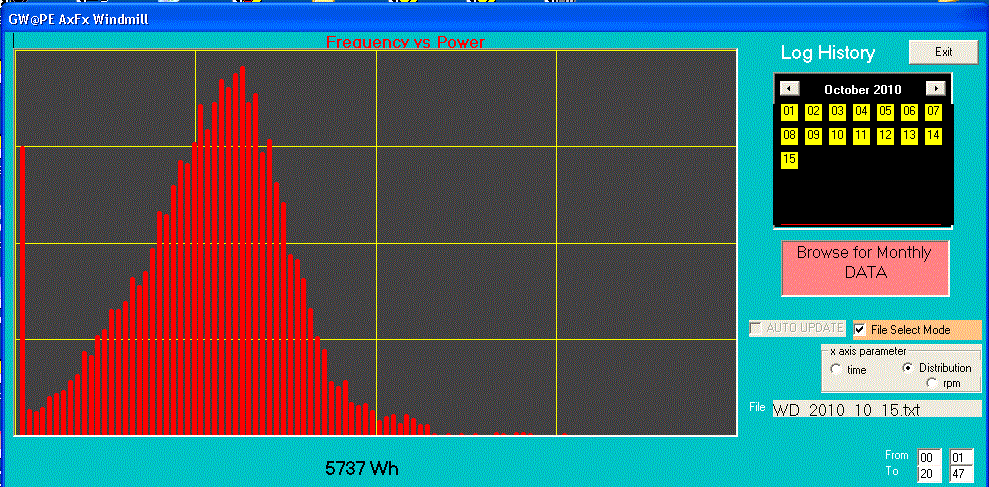
The weather was predicted to be setting in, so this was a good time to test. Here is a graph of the performance distribution today.

The new blades work very well with the furling settings for the mill. The windmill no longer has the big number outputs, but as the furling is more controlled, the windmill has now produced more power, in a more controlled way than ever before.
The windmill with the other blades would have produced a much wider range of power outputs. The distribution of power usually followed a negative exponential frequency of increasing power. The power distribution with the new blades follows a more normal distribution.
The new blades now hold rpm and the mill stays locked into the wind direction. The blade profile is high aspect and thin section, with long narrow tip sections. I have presented pictures earlier in this thread.
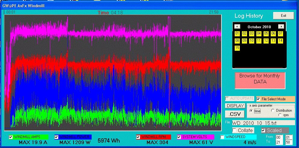
here is the graphed, logged data for today:-

It seems that the blades have a torque reducing property that works in harmony with the side furling and the loading. This results in lower peak power spikes. The small tip sections are unable to provide a high enough torque to drive the alternator to the really high power. The blades start to stall and the power plateaus as the furling starts to play a part.
The bottom end power does not seem to be affected. The blades respond rapidly to changing wind conditions in the low wind speeds, and speed limit at the higher windspeeds. I had been planning on making an electronic type speed limiting/loading system to do this.
The winding configuration of the alternator does overload these blades, so less turns would be in order to get a better match.
I will be exploring a way of getting some video uploaded of the electrical brake and the furling in operation during these latest windy conditions. The rotor seems to slow in around 1 revolution from 300rpm or about to under 5rpm. There is no apparent tower movement, or adverse yaw from the windmill.
This mill should be an ideal candidate for an SSRelay electronic brake. I have some more plans for another electronic MPP Tracking system as well. I am hoping to update the MPP settings at 100Hz. I have not given up yet on the micro approach.
Gordon.
become more energy aware |
| |
VK4AYQ
Guru

Joined: 02/12/2009
Location: AustraliaPosts: 2539 |
| Posted: 01:52pm 15 Oct 2010 |
 Copy link to clipboard Copy link to clipboard |
 Print this post |
|
Hi Gordon
Very impressive
Bob
Foolin Around |
| |
| |
  Page 12 of 12 Page 12 of 12 |

