|

|
Forum Index : Windmills : Staggered Stators
| Author | Message | ||||
| dannyboy43 Newbie Joined: 10/01/2017 Location: United StatesPosts: 2 |
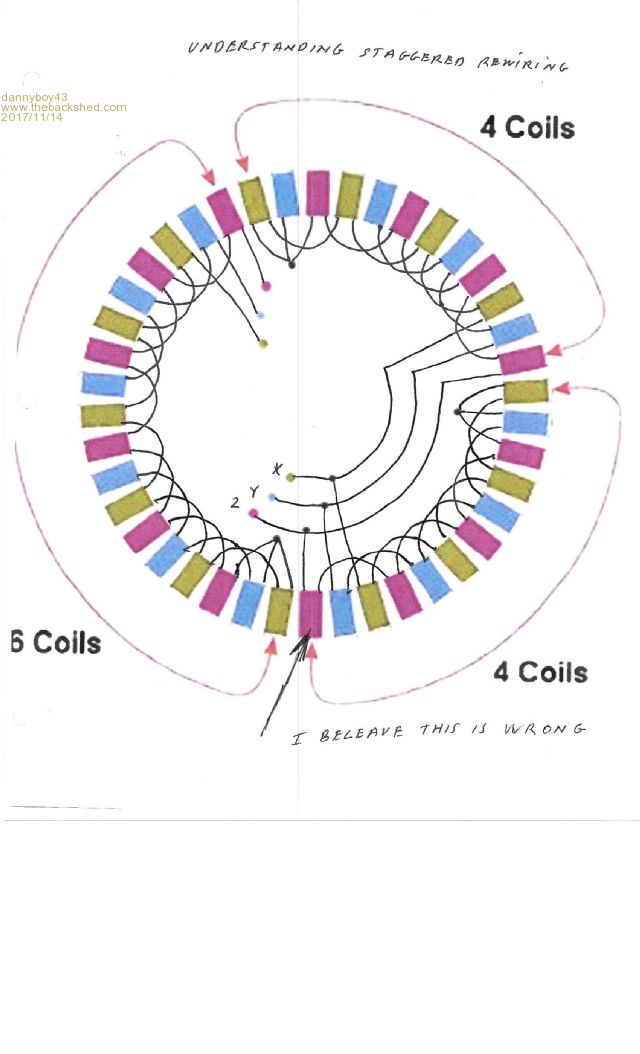
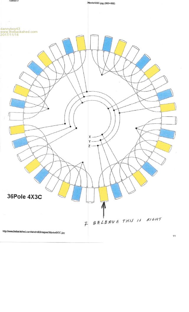
My 42 ploe / 80 /0.8mm wire. In the area of (Understanding Staggered Stators), there are 3 diagrams that of 2X7C, 1X9C 1X5C, 2X7C, and 1X6C 2X4C. As you know these are all 42 pole. They are wired using left side of red blue and yellow, going to Z, Y, and X. That is the total opposite of all that I see in all of the 36 ploe ( 2X6C, 6X2C, 3X4C, 6x2C, and last 4X3C. Please help me understand what I'm up against. Could it be I have the wrong 42 pole for the lay-out of my choice. Or are the lay-outs made in error, I hope I'm wrong on that point! I am just worried as to why the 36 pole and the 42 pole connecting to Z,Y,& X are different? Hoping to start right to end up right. By the way my phototype wind generator is a 6 pod vortek unit to be placed on the roof of my home. All of the mechanic's ironed out, with total smooth functioning. Thank you for being there for me. Kind Regards: Dan............ P/S my hats off to you for a great web site danby5_1@hotmail.com |
||||
| flc1 Senior Member Joined: 20/11/2011 Location: New ZealandPosts: 242 |
Hi Dan Not really sure what you mean when you say you use left side of red blue and yellow, is that your outlet wires of your stator(or inlet if in washing machine), is it a fisher n paykel stator? if you are talking about the outlet/inlet wires of the stator then it does not matter what color goes where because its ac coming out of the stator going to a rectifier or ac controller , need more details from you, of what you have there,what its going to be connected to etc, maybe a photo? |
||||
| dannyboy43 Newbie Joined: 10/01/2017 Location: United StatesPosts: 2 |
HI: I had a feeling that this was out side the norm. If you would look at the Wind power format that of ( understanding staggered stator's) F&P stator rewiring, the first 3 terminal (poles) going to Z Y and X are different starting points then that of the 3-4 diagrams understanding staggered rewiring are. Even if you look at a F&P factory wiring, you will see the images, the one's I'm making reference to are back-word of all the rest. ? is this, as the images shows the proper way to start the rewiring s or is it a typo? I feel bad that I didn't make mention that they are aLL F&P STATOR's    Here's hoping that these 2 images will draw your attention to my query Kind regards: Dan Mazurek danby5_1@hotmail.com |
||||
fillm Guru Joined: 10/02/2007 Location: AustraliaPosts: 730 |
Hi Dan, Yea I think I see what you mean, if it is the wire positions on the coils as the start and finish of 1 coil then yes the top 2 are wrong , the finish or end of the coil comes of on the left in reality if facing it and its pointing to you . PhillM ...Oz Wind Engineering..Wind Turbine Kits 500W - 5000W ~ F&P Dual Kits ~ GOE222Blades- Voltage Control Parts ------- Tower kits |
||||