|

|
Forum Index : Microcontroller and PC projects : MuP
| Page 1 of 2 |
|||||
| Author | Message | ||||
bigmik Guru Joined: 20/06/2011 Location: AustraliaPosts: 2914 |
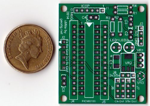
Gday Lads, The MuP (Mick's uMite PCBC) PCBs have just arrived.. and I must saw they look excellent. Now the big build and smoke test.. Although I have gone over it many times and not found any tracing problems, you never know. 
I have decided that costing will be $3 per PCB and shipping is $1 per order in AUS and $3 to most other countries. This freight would allow about 5 PCBs to be sent in a standard letter with no insurance. Payment is via paypal (or beer), or cash if anyone has any these days. Each PCB weighs 7gm and an air mail letter is supposed to be 50gm or under at that rate (and goes up on a logarithmic scale over 50gm). It would be cheaper to send 2 lots of 5PCBs if you needed 10 PCBs. I will keep you posted on how the build goes. 
Regards, Mick Mick's uMite Stuff can be found >>> HERE (Kindly hosted by Dontronics) <<< |
||||
| Geoffg Guru Joined: 06/06/2011 Location: AustraliaPosts: 3196 |
Great looking board Mick. I love the creativity on this forum! Geoff Geoff Graham - http://geoffg.net |
||||
| BobD Guru Joined: 07/12/2011 Location: AustraliaPosts: 935 |
Errr Mick, what's that brown thing next to the board in the photo? |
||||
Bryan1 Guru Joined: 22/02/2006 Location: AustraliaPosts: 1345 |
I'll hazard a guess and say an 18c coin afterall the rest goes in tax's....... Nice looking boards too Mick |
||||
bigmik Guru Joined: 20/06/2011 Location: AustraliaPosts: 2914 |
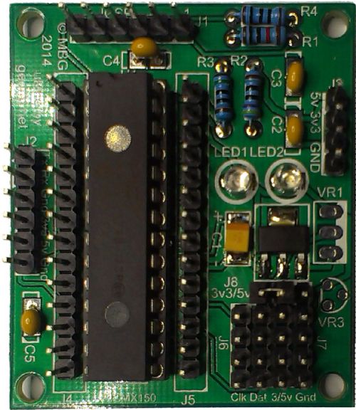
Lads, She LIVES! Here is a pic of a built up one.. 
I flashed the v4.5 Firmware into the PIC using the ICSP header (a song and dance as for some reason my pickit3 stopped working on win 8.1 but thanks to my win 7 box...) I have also tested the Console for communication and tested all outputs (one at a time) and it appears to work as expected. Regards, Mick Mick's uMite Stuff can be found >>> HERE (Kindly hosted by Dontronics) <<< |
||||
jman Guru Joined: 12/06/2011 Location: New ZealandPosts: 711 |
Well done Mick Board looks great Regards Jman |
||||
bigmik Guru Joined: 20/06/2011 Location: AustraliaPosts: 2914 |
Thanks Jman, I appreciate that.. It was a piece of cake to build also ... took me about 30-40min.. (after scrounging in my pile of junk looking for all the bits) Regards, Mick Mick's uMite Stuff can be found >>> HERE (Kindly hosted by Dontronics) <<< |
||||
| WhiteWizzard Guru Joined: 05/04/2013 Location: United KingdomPosts: 2817 |
Mick, Nice looking unit. I'll take 5 boards if thats ok for the UK. PM me paypal details and I will shoot you the beer money along with my details! PS - are you ok if I advertise these on MicroMite.org? We can chat on PM regarding this if you prefer. WW For everything Micromite visit micromite.org Direct Email: whitewizzard@micromite.o |
||||
bigmik Guru Joined: 20/06/2011 Location: AustraliaPosts: 2914 |
WW, Thanks, I will PM you now. Mick EDIT*** Of course you can advertise them.. I would be flattered.. EDIT 2 *** To those of you who expressed an interest via PM (before today) please resend if you are still interested as I accidentally deleted ALL of my PMs as my inbox was nearly full.. I tagged the ones I wanted to deleted and then clicked DELETE ALL DoH!!!! Anyway no major drama, PM me if still interested. Mick Mick's uMite Stuff can be found >>> HERE (Kindly hosted by Dontronics) <<< |
||||
| paceman Guru Joined: 07/10/2011 Location: AustraliaPosts: 1329 |
Ditto as per the others Mick - looks great. Would you send me five please, I'll PM details. Greg |
||||
bigmik Guru Joined: 20/06/2011 Location: AustraliaPosts: 2914 |
Bob, It is supposed to be GOLD (AUS $1 coin) but you are right with the way tax and utility charges are going here it is worth a lot less but then the physical size is still the same so for size comparisons it is still valid. 
Regards, mick Mick's uMite Stuff can be found >>> HERE (Kindly hosted by Dontronics) <<< |
||||
bigmik Guru Joined: 20/06/2011 Location: AustraliaPosts: 2914 |
OMG!! 
Already 30 of my order of 50 MuP PCBs are gone, I may have to do another batch of them (Or double the price to slow sales  ) )
MuP has gone international with 5 countries including Australia being recipients.. Thank you all for your support. It has been very appreciated. Regards, Mick Mick's uMite Stuff can be found >>> HERE (Kindly hosted by Dontronics) <<< |
||||
| paceman Guru Joined: 07/10/2011 Location: AustraliaPosts: 1329 |
Doesn't surprise me Mick, that's why I got in early 
Nice to see you can't keep a good man down! Greg |
||||
bigmik Guru Joined: 20/06/2011 Location: AustraliaPosts: 2914 |
paceman, Yours is on its way to you Greg, Don't stress... 
I wasn't doing this to get rich, although the thought is nice HaHa.. 
As I said before I wanted to do some for myself and there seemed a lot of interest. If I get another batch done I will try to add pullups for the I2C, They are missing on the one on offer now, not that it is a major problem. Regards, Mick Mick's uMite Stuff can be found >>> HERE (Kindly hosted by Dontronics) <<< |
||||
| MOBI Guru Joined: 02/12/2012 Location: AustraliaPosts: 819 |
@Mick, That would be ok for low speed I2C but if things change and higher speeds are catered for, lower values of resistors may be required. I use a 4 wire bus and plug in the appropriate resistors on a spare header on the bus. David M. |
||||
| Geoffg Guru Joined: 06/06/2011 Location: AustraliaPosts: 3196 |
If you add fixed pullups they will interfere with using the I/O pins for general duties (ie, non I2C). Geoff Geoff Graham - http://geoffg.net |
||||
bigmik Guru Joined: 20/06/2011 Location: AustraliaPosts: 2914 |
Hmm, Thanks Mobi, Geoff, Both good points.. I knew there was a reason I forgot to put them on the PCB.. 
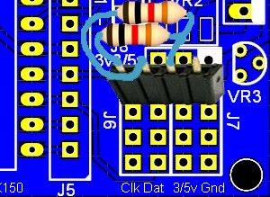
Excuse the bad quality picture but I had as one option something like this on one of the sets of 4 pins I assigned for I2C. I intend to do a proper photograph of one to include in the manual (Well Maybe closer to documentation than manual) but I think the idea is clear enough. 
The only other thing I thought of was a possible 1k resistor on the RX console if a 5V TTL adapter was used but even that there are times when you want it and times when you dont. It is not hard to add a resistor to your cable if you need it.. I think I have to bite the bullet and get some more done as it has only been 1 day and I am down to 15 left. Regards, Mick Mick's uMite Stuff can be found >>> HERE (Kindly hosted by Dontronics) <<< |
||||
| vasi Guru Joined: 23/03/2007 Location: RomaniaPosts: 1697 |
My I2C connector on board have jumpers for the pull-ups. http://myshed.files.wordpress.com/2012/09/sanguino4-2.png http://myshed.files.wordpress.com/2012/09/p1070689.jpg Hobbit name: Togo Toadfoot of Frogmorton Elvish name: Mablung Miriel Beyound Arduino Lang |
||||
bigmik Guru Joined: 20/06/2011 Location: AustraliaPosts: 2914 |
Hi Vasi, Good pictures, but it looks like someone has chewed the top off your RESET switch.. 
Your PCB is much larger than the MuP and to add extra jumpers and at least 2 different types of resistors (depending on speed) is really not an option.. Whilst I think I `could' squeeze it all in the clutter of jumpers would then start to be very confusing. Better to keep it neat and simple, I think.. after all you can always mount the pullups on the target device.. Regards, Mick Mick's uMite Stuff can be found >>> HERE (Kindly hosted by Dontronics) <<< |
||||
| paceman Guru Joined: 07/10/2011 Location: AustraliaPosts: 1329 |
Hi Mick, Received mine this morning and they look great - that'd have to be a record: from inception to production to inventory and then customer via the post! Still looking at how I'll connect my UV exposure box project with it (it's only been a couple of hours) but here are some quick thoughts for V2 if you're doing it. 1. Pullups could be optional via jumpers or solderlink. 2. Same for the 1K resistor on the pin12 Rx line in. 3. Putting all connector headers and the PIC on a 0.1" grid would make using it with proto boards a doddle - the components don't need to be on the grid. Greg |
||||
| Page 1 of 2 |
|||||