|

|
Forum Index : Microcontroller and PC projects : 3.3V LCD
| Author | Message | ||||
jman Guru Joined: 12/06/2011 Location: New ZealandPosts: 711 |
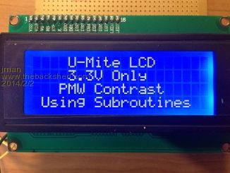
Hi All Playing with the new MicroMite I wanted to drive a 4x20 lcd After a quick look at the LCD datasheet the supply voltage range is 2.7 to 5.5 so no problem there. The problem is with the supply at 3.3v the contrast pin needs a negative voltage. I used a PMW output and this simple circuit and now we have software adjustable contrast with 3.3v only. I have attached the modified LCD program You can use 1n4148's in place of the Bat54s's 
2014-02-02_071102_UMiteLCD.zip Regards Jman |
||||
| OA47 Guru Joined: 11/04/2012 Location: AustraliaPosts: 926 |
Good thinking Jman. I'm impressed. |
||||
| MOBI Guru Joined: 02/12/2012 Location: AustraliaPosts: 819 |
Nifty. One up on me. 
I use PWM for backlight control but not contrast. David M. |
||||
| kiiid Guru Joined: 11/05/2013 Location: United KingdomPosts: 671 |
I am not a popular poster around, but from own experience I believe this circuit is a bit pointless and can be significantly optimised. The negative contrast voltage is relative to the power supply and is internally generated. From outside you can do variable contrast by simply connecting Vlcd through 1k (typically) resistor in series to a PWM output. Usually in the devices the LCD contrast is fixed (with 1k to ground) and the backlight is PWM controlled. http://rittle.org -------------- |
||||
Grogster Admin Group Joined: 31/12/2012 Location: New ZealandPosts: 9308 |
Well, yeah, the common method I have seen, is to connect a 1K trimpot between VLCD and ground. You just twiddle the trimpot to get the best contrast - set it, and forget it. Still, not to take away from jman's experiments, though, kiiid....  Smoke makes things work. When the smoke gets out, it stops! |
||||
| kiiid Guru Joined: 11/05/2013 Location: United KingdomPosts: 671 |
Sure. Experiment is the path to invention. I just wanted to help to make it better. http://rittle.org -------------- |
||||
jman Guru Joined: 12/06/2011 Location: New ZealandPosts: 711 |
Hmm I don't think so With +5V Vcc the Vlcd can be obtained from the same +5V Vcc voltage by using a resistor voltage divider or a pot, while with +3.3V Vcc this requires a negative voltage source (from 3.3V-5.5v=-0.2V to 3.3V-5V=-1.7V). Jman |
||||