|

|
Forum Index : Microcontroller and PC projects : Maximite Book
| Author | Message | ||||
CircuitGizmos Guru Joined: 08/09/2011 Location: United StatesPosts: 1425 |
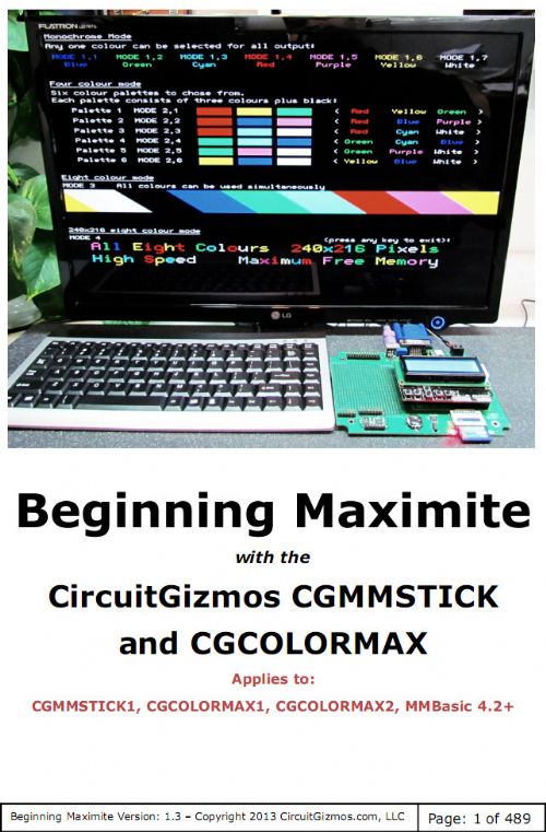
Wow. At 480 pages long this has become a book. Beginning Maximite 1.3 is available for download. If anybody has questions or comments, please bring them up here. I would like to know if there is anything missing that could be added to this .pdf There is a thank you in the book to this forum. I appreciate all of the feedback. Beginning Maximite 
Micromites and Maximites! - Beginning Maximite |
||||
| johnbig Newbie Joined: 23/06/2011 Location: AustraliaPosts: 21 |
Hi CircuitGizmos, Do you think that the following should be mentioned in your book or on your website somewhere for new people who aren't familiar with this web site. Kind Regards John Leate R6 is supposed to be a 120k resistor and it is incorrectly a 1k resistor. |
||||
CircuitGizmos Guru Joined: 08/09/2011 Location: United StatesPosts: 1425 |
Ah. Good point. Micromites and Maximites! - Beginning Maximite |
||||
elproducts Senior Member Joined: 19/06/2011 Location: United StatesPosts: 282 |
What a ton of effort that took. Fantastic reference. Thanks for sharing it. www.elproducts.com |
||||
| centrex Guru Joined: 13/11/2011 Location: AustraliaPosts: 320 |
Hi gizmos I have just built a home brew version of the lcd shield and it all works with your software, very pleased. I have adjusted the resistors values to work within the 3.3volt analog range so I can read all 5 switches. I have also added a temperature sensor an LM335 which tried connecting to A5 I/O 40. This would not work further checking with the sensor connected to I/O 38 and all is ok. Further testing of I/o 39 and 40 with a resistor voltage divider giving 2.5volts and the pins set to analog input I get no valid readin. Is this normal , I have checked the continuity through to the bottom of the colour maximite and this is ok. From their on I cannot trace the tracks are to small to check continuity. In your manual page 412 you llist all the pins 35 to 40 as analog but NOT 5 volt tolerant, with no switches pressed on the lcd shield their is 5volts at pin 35 is this ok. regards cliff Cliff |
||||
CircuitGizmos Guru Joined: 08/09/2011 Location: United StatesPosts: 1425 |
I dropped the ball on pins 39 and 40 (A4/A5). I meant to write out a paragraph in the document explaining that just like the original Colour Maximite, there are two places that this connection can come from. In the Colour Maximite schematic, you can see the J2, J3 jumper/headers. On the CGCOLORMAX they are J14 and J15 - see page 463 for information. I'll add descriptive information for the next BegMax release. The switch and resistor circuit should be powered from 3.3V - then no switches pressed would be 3.3V (not 5V) and each switch press would be a different voltage less than 3.3V. Micromites and Maximites! - Beginning Maximite |
||||
| Bugs2 Newbie Joined: 18/05/2012 Location: United KingdomPosts: 29 |
Many thanks for the effort expended on this helpful documentation. The really 'good thing' about an on-line book is that it's never finished! |
||||
CircuitGizmos Guru Joined: 08/09/2011 Location: United StatesPosts: 1425 |
Jeez! I KNOW!   Micromites and Maximites! - Beginning Maximite |
||||
| centrex Guru Joined: 13/11/2011 Location: AustraliaPosts: 320 |
Thank Gizmos I overcame the voltage problem by changing the 2K resistor at the start of the divider chain to 4.7K and adding a 1K resistor to gnd at the end of the chain. It would have been easier to run the divide from the 3.3volt rail. Thanks for the info. Regards Cliff Cliff |
||||
Grogster Admin Group Joined: 31/12/2012 Location: New ZealandPosts: 9307 |
WOW! 
JUST WHAT I NEEDED!!!! As a relatively new comer to MM, I was looking around for some sort of detailed documentation(other then what is already available on Geoff's site, and what you can find out here, naturally), then stumbled on this thread. Fantastic, and thank you for sharing. 
...might take me a few days to read 400+ pages though... 
(not that that is a complaint - it isn't) Smoke makes things work. When the smoke gets out, it stops! |
||||
CircuitGizmos Guru Joined: 08/09/2011 Location: United StatesPosts: 1425 |
Thanks! Micromites and Maximites! - Beginning Maximite |
||||