|

|
Forum Index : Microcontroller and PC projects : Vacuum Fluorescent Display test
| Author | Message | ||||
CircuitGizmos Guru Joined: 08/09/2011 Location: United StatesPosts: 1425 |
I've had a couple of these display modules setting around for a while. They have a 10-pin connector, not the 'normal' 14 that an LCD module has. I also don't have a data sheet for the display, but a couple of old data sheets for different displays. Every time I bump into the modules in my box of stuff I wonder what they look like when activated. 
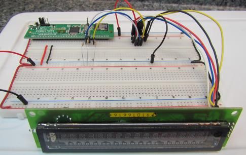
But it has always been a bother to try to figure out if any of the datasheets apply, if any do at all. Today I decided to wire up the display to a CGMMSTICK to play around with them. It is a 5V display, so I used OC outputs pulled to 5V through a 10k resistor. The display has a reset line, data in, and clock. Data is most significant bit first. Pins 2, 4, 6, 8, 10 are ground Pin 1 +5V Pin 3 clock Pin 5 data Pin 7 reset 
The value that it takes to write "A" is 1, "B" is 2. This doesn't follow ASCII. Below is the code I used to test the display: ' VFD test code ' I/O init ' Open collector data SETPIN 12, 9 : PIN(12) = 1 ' Open collector clock SETPIN 13, 9 : PIN(13) = 0 ' Open collector reset SETPIN 15, 9 : PIN(15) = 1 ' Values for characters _A = 1 : _B = 2 : _C = 3 : _D = 4 : _E = 5 : _F = 6 : _G = 7 : _H = 8 : _I = 9 : _J = 10 _K = 11 : _L = 12 : _M = 13 : _N = 14 : _O = 15 : _P = 16 : _Q = 17 : _R = 18 : _S = 19 _T = 20 : _U = 21 : _V = 22 : _W = 23 : _X = 24 : _Y = 25 : _Z = 26 _AT = 0 : _SPACE = 32 _ZERO = 48 : _ONE = 49 : _TWO = 50 : _THREE = 51 : _FOUR = 52 : _FIVE = 53 _SIX = 54 : _SEVEN = 55 : _EIGHT = 56 : _NINE = 57 ' Initialize and send characters ' Reset and init LCD VFDRESET VFDDATA _SPACE VFDDATA _T VFDDATA _H VFDDATA _E VFDDATA _SPACE VFDDATA _B VFDDATA _A VFDDATA _C VFDDATA _K VFDDATA _SPACE VFDDATA _S VFDDATA _H VFDDATA _E VFDDATA _D VFDDATA _SPACE END ' VFD display reset routine Sub VFDRESET ' pulse the reset line PIN(15) = 1 : PAUSE 1 PIN(15) = 0 : PAUSE 1 PIN(15) = 1 : PAUSE 1 ' Clear the display VFDDATA &h20 VFDDATA &h20 VFDDATA &h20 VFDDATA &h20 VFDDATA &h20 VFDDATA &h20 VFDDATA &h20 VFDDATA &h20 VFDDATA &h20 VFDDATA &h20 VFDDATA &h20 VFDDATA &h20 VFDDATA &h20 VFDDATA &h20 VFDDATA &h20 VFDDATA &h20 ' Turn display on VFDDATA &hFF End Sub ' Write data to display, MSB first Sub VFDDATA (valu) PIN(13) = 1 PIN(12) = valu AND &B10000000 PIN(13) = 0 : PIN(13) = 1 PIN(12) = valu AND &B01000000 PIN(13) = 0 : PIN(13) = 1 PIN(12) = valu AND &B00100000 PIN(13) = 0 : PIN(13) = 1 PIN(12) = valu AND &B00010000 PIN(13) = 0 : PIN(13) = 1 PIN(12) = valu AND &B00001000 PIN(13) = 0 : PIN(13) = 1 PIN(12) = valu AND &B00000100 PIN(13) = 0 : PIN(13) = 1 PIN(12) = valu AND &B00000010 PIN(13) = 0 : PIN(13) = 1 PIN(12) = valu AND &B00000001 PIN(13) = 0 : PIN(13) = 1 End Sub And the result: 
I don't know if any displays like this one show up as surplus, but if they do, this test code will help get them working. Micromites and Maximites! - Beginning Maximite |
||||