|

|
Forum Index : Microcontroller and PC projects : EasyPIC Fusion
| Author | Message | ||||
| vasi Guru Joined: 23/03/2007 Location: RomaniaPosts: 1697 |
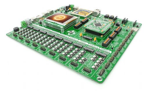
Well, I said it few times - develop on PIC24 and burn the final application on PIC32. Mikroelektronika did it: 
Hobbit name: Togo Toadfoot of Frogmorton Elvish name: Mablung Miriel Beyound Arduino Lang |
||||
| JohnS Guru Joined: 18/11/2011 Location: United KingdomPosts: 3801 |
It's rather expensive!! John |
||||
elproducts Senior Member Joined: 19/06/2011 Location: United StatesPosts: 282 |
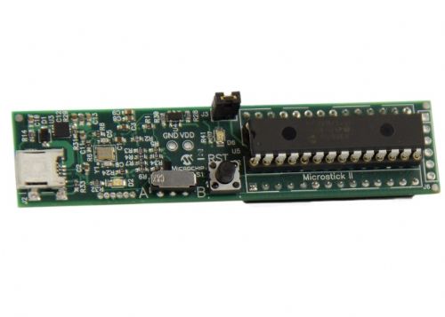
You could just use the Microchip Microstick II. It even comes with a PIC24F, PIC24H, dsPIC33 and PIC32 DIP and built in programmer/debugger. All for $35. Plugs right into a breadboard. Wish these PIC32 DIPs had enough memory to run Maximite. There are so many simple, small, easy to kit/build gadgets you could create with a Maximite DIP chip. 
www.elproducts.com |
||||
MicroBlocks Guru Joined: 12/05/2012 Location: ThailandPosts: 2209 |
A PIC32MX130F064B should be able to run a modified MMBasic. If you take out the video routines and maybe some other parts that are not usefull for a chip like that you might be able to get it in the 64KB flash. It has 16Kb ram and according to the mmbasic.com website that should be the minimum to run mmbasic. Microblocks. Build with logic. |
||||
| vasi Guru Joined: 23/03/2007 Location: RomaniaPosts: 1697 |
Of course I don't have money for that board but if it is to be 100 pin PIC24/32 development board, then it has to be that board. No compromises. For complex applications and for commercial applications this board is great. For DIP packages I will rater stay with PIC18F/ATmega, at 5V, as I'm doing it already. Hobbit name: Togo Toadfoot of Frogmorton Elvish name: Mablung Miriel Beyound Arduino Lang |
||||
| DuinoMiteMegaAn Senior Member Joined: 17/11/2011 Location: AustraliaPosts: 231 |
The totaL cost for the Fusion v7 Pic Development "Kit" which includes the PIC32 micro adapter and software for only $440 USD. Too steep for my wallet. 
One thing I did noticed is their top secret, advance technology "Mikro bus" which they said "covers 80% of interfacing requirements" A hacker could install an Olimex Arduino proto shield on top of the Color Maximite, add two 8 pin headers on the shield and use MikroElektronka's assorted 31 Click boards on the Color Maximite.  The only unknown is whether SPI is available on the Arduino shield pins on the Color Maximite ??? Maybe GeoffG can chime in on this question. The only unknown is whether SPI is available on the Arduino shield pins on the Color Maximite ??? Maybe GeoffG can chime in on this question.
BTW ... MikroBus Specs 2012-09-04_012039_mikrobus_specification.pdf microSD click ADC click DIGI POT click RS485 click 5V MP3 Click Buzz Click RTC Click RTC2 click DAC Click SHT11 click EXPAND click GPS Click Bluetooth Click ETH Click BEE click RS485 click 3.3V LightHz click CAN SPI click 3.3V CAN SPI click 5V GPS Click - L10 WiFi Plus Click Accel click IrDA2 click OPTO click THERMO click Flash Click EEPROM Click 7seg click USB UART click USB SPI click 4-20 mA T click |
||||
bigmik Guru Joined: 20/06/2011 Location: AustraliaPosts: 2914 |
Hi DMM, I think that is what J2 and J3 is on the schematic are for... SPI or I2C. I havent been able to read the article yet as SC online still hasnt posted it.... (what a waste of $76) Regards, Mick Mick's uMite Stuff can be found >>> HERE (Kindly hosted by Dontronics) <<< |
||||
TassyJim Guru Joined: 07/08/2011 Location: AustraliaPosts: 6098 |
From the Maximite hardware manual on Geoff's website: Arduino Compatible I/O Connector
The Colour Maximite has an additional 20 I/O pins (40 in total) on the Arduino compatible connector. These are independent of the I/O pins on the back panel. The designation of the Arduino pins are printed on the PCB and follow the standard layout numbering D0 to D13 and A0 to A5. You can use the labels D0, D1, etc in MMBasic statements or you can use their corresponding numbers (D0 = 21, D1 = 22, etc and A0 = 35, A1 = 36, etc). The digital pins (D0 to D13) have the same characteristics (5V, open collector, etc) as the digital pins 11 to 20 and the analog capable pins (A0 to A5) have the same capabilities as pins 1 to 10. Many Arduino systems make the I2C available on connector pins A4 and A5. Using the jumpers (J2 and J3) you can select between the normal I/O function for these pins (A4 and A5) or the I2C signals (SCL and SCA). Note that these I2C signals are also available on the external I/O pins 12 and 13 on the back panel so effectively these jumpers join these I/O pins together when in the I2C position. No need to wait for SC. Jim VK7JH MMedit MMBasic Help |
||||
| DuinoMiteMegaAn Senior Member Joined: 17/11/2011 Location: AustraliaPosts: 231 |
Ok ... I2C is available on the Arduino header but is SPI (MOSI/MISO/SS) also available? The DuinoMite Mega had the SPI (SD card) multiplexed on their Ardunio pins which ended up being a total disaster. 
Also, I like to mention that even though the MikoBus Click boards could be added to the Color MaxiMite there could be other problems like pullups/pulldowns, 5v/3.3v logic and bus speed problems due to MMBasic speed.  |
||||
elproducts Senior Member Joined: 19/06/2011 Location: United StatesPosts: 282 |
I haven't tried it but based on the MMBasic Language manual Appendix D, it appears that MMBasic is just bit-banging SPI so any set of digital pins will work. The syntax of the function is: received_data = SPI( rx, tx, clk, data_to_send, speed, mode, bits ) Data_to_send, speed, mode and bits are all optional. If not required they can be represented by either empty space between the commas or left off the end of the list. Where: �rx� is the pin number for the data input (MISO) �tx� is the pin number for the data output (MOSI) �clk� is the pin number for the clock generated by MMBasic To match the Arduino header setup: SPI: 10 (SS), 11 (MOSI), 12 (MISO), 13 (SCK). Try using this in MMBASIC: received_data = SPI( D12, D11, D13, data_to_send, speed, mode, bits ) www.elproducts.com |
||||
| DuinoMiteMegaAn Senior Member Joined: 17/11/2011 Location: AustraliaPosts: 231 |
So you are saying that the Color MaxiMite Arduino shield pins has software SPI and NOT a hardware SPI? Sounds reasonable but for driving other Arduino shields HW SPI is preferred. I believe the PIC32 has several hardware SPI buses (up to 4 SPI modules) available.  |
||||
| paceman Guru Joined: 07/10/2011 Location: AustraliaPosts: 1329 |
The Sept. Silicon Chip colour MM article (p24) explains it. The 64 pin PIC32 had 3 SPI outputs, the 100 pin PIC32 has 4 SPI outputs. In the colour MM though, 3 of the SPI's are needed to generate the colours and the 4th is still needed for the SD card. That leaves no hardware SPI's left, so bit-banging it is. On the plus side though, you get to choose which pins. Greg |
||||
| vasi Guru Joined: 23/03/2007 Location: RomaniaPosts: 1697 |
Which is enough, in my opinion... It can be used as a bus for as many devices you can use. But I guess now is too late for the hardware design... Hobbit name: Togo Toadfoot of Frogmorton Elvish name: Mablung Miriel Beyound Arduino Lang |
||||
| vasi Guru Joined: 23/03/2007 Location: RomaniaPosts: 1697 |
The other board from mikroe, used as "dock station" for mikromedia boards: http://vimeo.com/44921142 So much elegance!  Hobbit name: Togo Toadfoot of Frogmorton Elvish name: Mablung Miriel Beyound Arduino Lang |
||||