|

|
Forum Index : Microcontroller and PC projects : Hardware Help...
| Author | Message | ||||
crackerjack Senior Member Joined: 11/07/2011 Location: AustraliaPosts: 164 |
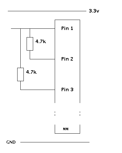
Hi all, my hardware skills are, well, not. Not skills at all; however like Manuel said to Basil "But I learn, Mr. Fawlty - I learn." The thing is I am not keen to fry my Maximite as part of the learning process and so I turn to you dear Forum fraternity to offer some helpful hints... I am wanting to use an Analog in pin (let's just say Pin 1) to detect a logic High, Low and Hi-Z state on the output of another device. I also want this pin (Pin 1) to serve as a digital in at another time (let's say another mode) of the same program. My guess at this would be to wire up the circuit as follows: 
And then when I want to check for the Low/High/Hi-Z state, to set Pin 2 and 3 as outputs, set Pin 2 High, Pin 3 Low thereby creating a voltage divider on Pin 1 (which will at this stage be set to Analog In). Then the plan is to measure the voltage on Pin 1 which is connected to the output of the other circuit. If that output is high, it should pull the voltage high on Pin 1, if Low, will pull the voltage low on Pin 1, if neither, Pin 1's voltage will be somewhere between the two thanks to the voltage divider (thus Hi-Z state is detected on the "output" of the other circuit). Does this sound fair? I wan't to be able to switch this behaviour on/off by using Pin 2 & 3 as decscribed so that Pin 1 can be used to measure variable voltage too in the other mode of operation. I realise this is very simple stuff, but we all start somewhere, right? Also, this test will be limited to checking outputs at 3.3v and less only, correct? No way to test levels at 5 volts with this on the MM with the Analog In's limited to 3.3 volts? Thanks in advance for any help. |
||||
crackerjack Senior Member Joined: 11/07/2011 Location: AustraliaPosts: 164 |
Ok, I did the experiment (which is what I should have done first) and it works as I had hoped. Circuit as above and a bit of guidance on logic voltages and all is sweet. Simple logic probe then is the circuit above with this code: [code] SetPin 2,8 : Pin(2)=0 'Pull Low SetPin 3,8 : Pin(3)=1 'Pull High SetPin 1,1 ' Should be neither Low nor High Do v=Pin(1) If v<1 Then state$="Low " ElseIf v>2 Then state$="High" Else state$="Hi-Z" ' Possibly the Output under test is an Input EndIf If state$<>prev_state$ Then pulsed$="p" EndIf Print @(100,100) state$, pulsed$ prev_state$=state$ : pulsed$=" " Loop [/code] When fed a PWM signal at 3.2 kHz 50% duty cycle, the above little program detects the pulses pretty well too. I can't be sure it would detect a single short pulse, but I may experiment with that. It would need some sort of "pulse-stretching" code so that the value didn't strobe so much at that frequency. Anyway - lots of fun and learning always to be had. Cheers. |
||||
| Gizmo Admin Group Joined: 05/06/2004 Location: AustraliaPosts: 5078 |
Hi Crackerjack Good to see you worked it out, Geoff has some info on protecting the chip inputs here http://geoffg.net/MaximiteDesign.html under External I/O. The chip has protection diodes on the inputs, but a good spike can still damage it, so a resistor in series with any input is a must have. Glenn The best time to plant a tree was twenty years ago, the second best time is right now. JAQ |
||||
bigmik Guru Joined: 20/06/2011 Location: AustraliaPosts: 2914 |
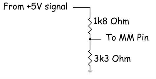
Hi CJ, You could of course wire them to +3.3v and GND with the same effect. Depending on what sort of source you are supplying the resistors wouldnt have any affect on a digital read... If you are supplying a voltage from a resistor divider then it may impact on the accuracy of the reading but you could use weak pull up/down (say 100k) and they should still do the job... Also to feed a 3.3v input with a signal of 5v you can use a resistor divider as shown here 
Regards Mick Mick's uMite Stuff can be found >>> HERE (Kindly hosted by Dontronics) <<< |
||||