|

|
Forum Index : Microcontroller and PC projects : Electronic Throttle Control Circuit
| Author | Message | ||||
| WindyMiller Regular Member Joined: 05/04/2011 Location: United StatesPosts: 62 |
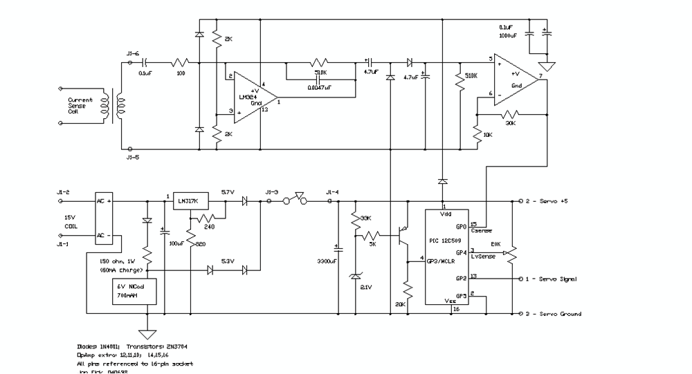
G'Day, I am interested in wether or not anyone would be interested in reviewing this pic based project? This controller was orginally available on Jon Fick's website Authors Site but was removed after the author sold the generator it was created for. I was able to obtain the pic program from Jon and is attached below for review. I am looking for any minor changes to the overall design that would result in better performance and operation of the circuit? Here is a little more information Jon provided when I contacted him about this circuit a little while back. I created that circuit for an old Craftsman generator that never worked very well. While the servo circuit and mechanical coupling worked, at least one issue was the carbureator which wasn't intend to run at one speed within the governed range, not throttleable from idle to full. But it worked. I wrote the code using a CCS C compiler for the 509. I used to have that project listed on my website http://www.vermontficks.org/pic.htm but removed it awhile ago because I got rid of the generator. I still have the code, though, which I've attached if it's any help to you. The currrent sense coil was simply the core of an old air solenoid whose signal was amplified and rectified by the op amps in the circuit. You'll see in the code listing a comment about the throttle curve needing to be table driven so as to not stall the engine. The circuit was built up on a perf board with yellow wires everywhere. These days I would have put it on a pcb from ExpressPCB or elsewhere. I hope that's helpful. Jon 
To date this is the only controller of it's kind I have been able to find on the web. If anyone has seen any others? I would be interested in seeing the links. Original design and program code by Jon Fick and is being shared here with his kind permission. Robert 2012-01-03_122612_Pic_Program.zip |
||||
| jwettroth Regular Member Joined: 02/08/2011 Location: United StatesPosts: 71 |
I'd be willing to help a bit with this. The best way might be to get a private email exchange or a phone call going. The analog portion is not completely clear to me. If I understand, the coil input senses the generator output. It's output gets filtered, rectified and then gained up in DC to go to a digital input pin. This is sort of voltage/tachometer setpoint. On a more modern mid range pic- (a 16F690?) a lot of this could be done with an ADC and some of this could be done in software. Another technique might be to use a counter input on the PIC and an opto reflector to make a tachometer circuit (Jon's circuit is a bit of a tachometer too even if its unintentional). This would be just an opto emitter and detector that looks at a stripe or two on the engine output shaft. Alternatively an automotive variable reluctance or hall sensor sensor could be used to sense RPM if this is the goal. If the goal is to measure output voltage then a ciruit like he has is a pretty good start but could be fed to an ADC to give you a lot more data. One of the issues (and potential dangers) of these types of systems is instabilities that can be caused by the long delays in the engine. The PIC is cranking along and making changes and the engine takes time to react. The control system has to be slow enough to keep from overshooting but fast enogh to keep the power output steady. In writing this post, I remember adding "cruise control" to my wife's car with an after market kit many years ago. You put a magnet on the drive shaft, set a speed and this little box would maintain it as you went up and down hills. It had a couple of little pots that let you adjust the loop for best performance. It worked ok but my dealer said that it would void my warranty so I took it off. I wonder if these after market things are still made? (J.C. Whitney Catalog?) Send me an private mail and we can set up a phone call to talk about it some. It looks like a bit of fun. Might be a lot of fun to throw at a Maximite computer- VGA display! Is this just a one off for your personal use or do you want to produce a product? Regards, John John Wettroth |
||||