|

|
Forum Index : Microcontroller and PC projects : (DM/MM) External Circuits
| Author | Message | ||||
Bryan1 Guru Joined: 22/02/2006 Location: AustraliaPosts: 1344 |
G'day Guy's, I've started this thread in the hope we can provide tips and schematics of how people are hooking up external circuits to the DM/MM. Not all of us (including me) are hardware guru's and I do feel a thread where schematics are shown could go along way into being a helpful thread for everyone. Like hooking up to the 3.3 volt ADC pins for 12,24 48 volts etc Resistors for pin protection against spikes etc Hooked up an Ethernet chip on an external board ? One can go on, but how about we make a start so everyone can get an idea on how about hooking up external circuits then more and more projects I'm sure will soon start coming. Regards Bryan |
||||
bigmik Guru Joined: 20/06/2011 Location: AustraliaPosts: 2914 |
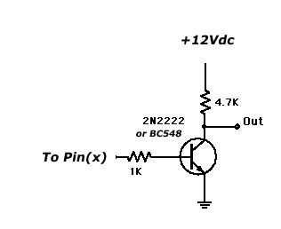
Gday Bryan, you can use the 3.3v Digital Output pins to drive higher voltages by using a transistor. Assuming you wish to drive a 12V relay you could use something like this cct. 
When the Pin(x) is High the relay would be off when Pin(x) is low the Relay would be on.. you need to watch the value of the resistor (in this case 4.7k) is not too high that the relay wont latch and not too low that the transistor would burn out Maybe start at 4.7k and drop down to say 1k .... As it is you can pulse 0-12V signals as the Pin(x) changes. regards, mick Mick's uMite Stuff can be found >>> HERE (Kindly hosted by Dontronics) <<< |
||||
| larny Guru Joined: 31/10/2011 Location: AustraliaPosts: 346 |
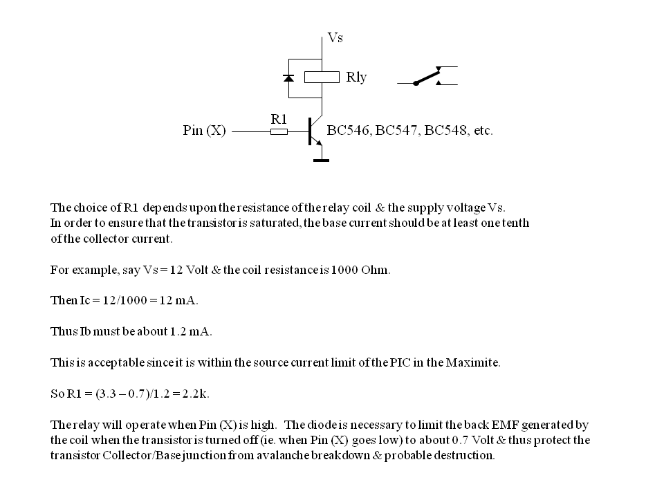
Here is my suggestion. Bryan, I'll comment on your other questions later. Len 
|
||||
| Pr0f Newbie Joined: 09/12/2011 Location: United KingdomPosts: 10 |
You can also add a resistor in series with the relay, and then add a capacitor of say 100u with +ve terminal connected to the bottom of the resistor and the relay coil, and the -ve electrode connected to 0v. Find the datasheet for your relay - it should quote 2 currents - pull in current and hold current - size the series resistor so that hold current specification is met. What the capacitor does is to provide a reserve of current to pull the relay in initially, when the transistor switches, but then the series resistor ensures only enough current flows to hold the relay. The addition of these 2 components make the circuit more suitable for use in battery powered equipment where currents need to be kept to a minimum. Logic level mosfets can be ideal as switching elements for relays - relays can't be switched that quickly so the frequency you can operate the relay at means that the effect of gate capacitance charge time is negligable and a high value gate resistor can be used between the pic output and the mosfet. |
||||
| larny Guru Joined: 31/10/2011 Location: AustraliaPosts: 346 |
A better way to do it is to connect a break contact (normally closed) in parallel with the resistor. So the operate current passes through the contact & then, when the relay operates, the current is reduced to the hold current level. I agree about the MOSFETs but you need to choose one that has a low gate threshold. Len |
||||
Bryan1 Guru Joined: 22/02/2006 Location: AustraliaPosts: 1344 |
Hi Guy's, Ok how would this circuit go for measuring the Vin out of a 24 volt batterybank. The 10K pot will give the required span and the 2.2K is there to protect the input pin along with the 3.3V zener on the rail. I have tried out this circuit on a breadboard before using the zeners I had onhand and it did give pretty good results. Regards Bryan |
||||
| larny Guru Joined: 31/10/2011 Location: AustraliaPosts: 346 |
Bryan, You may not need the 3V3 Zener. I'll check the data sheet of the PIC when I have time. There will be some thermal drift with the 22V zener, I'll check that too. The 22 V Zeners also have a spread around 22 Volt, I think, from memory, it is +/- 5%. Len |
||||
| JohnS Guru Joined: 18/11/2011 Location: United KingdomPosts: 3800 |
I'm feeling stupid. What's the point of the 22V Zener? John |
||||
| larny Guru Joined: 31/10/2011 Location: AustraliaPosts: 346 |
The Zener is in lieu of a resistive voltage divider (VD). A VD would reduce the voltage to a level that the MM can handle, but you would need about an 8:1 division ratio, ie. reduce 24 Volt to 3 Volt approx. The problem with this is that the VD also attenuates the change in the 24 Volt by the same ratio. So, for example, say the 24 Volt decreased to 23 Volt, the change seen by the MM will be 1/8 Volt. But if you use a Zener, then 24 Volt translates to about 2 Volt at the MM & there is no attenuation of the change. So, using the previous example, a change from 24 to 23 Volt means that the MM sees a 1 Volt change. Len |
||||