|

|
Forum Index : Microcontroller and PC projects : (MM-DM) Maximite RE Controller
| Page 1 of 3 |
|||||
| Author | Message | ||||
| Gizmo Admin Group Joined: 05/06/2004 Location: AustraliaPosts: 5078 |
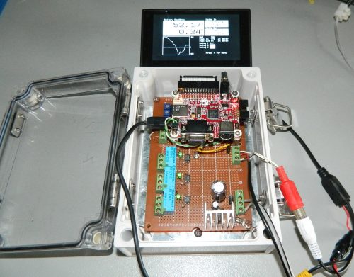
OK, this is a project I've been putting off too long, time to get it finished. I've built a few PicAxe based charge controllers in the past. One was a 28X based controller with LCD http://www.thebackshed.com/Windmill/articles/GizmoPicAxeChar ger.asp, and is still in use. The other used a 08M and was designed more for logging, but could be used as a controller http://www.thebackshed.com/Windmill/PicLog.asp. As soon as I first saw the Maximite early this year, I knew it would be the brains behind a more advanced controller. I wanted a controller that would regulate my battery bank, by controlling the solar/wind turbine supply, and track watt hours in and out of the battery bank, so I could tell at the end of the day if my batteries were gaining or loosing charge, and take action if needed. This is it so far. 
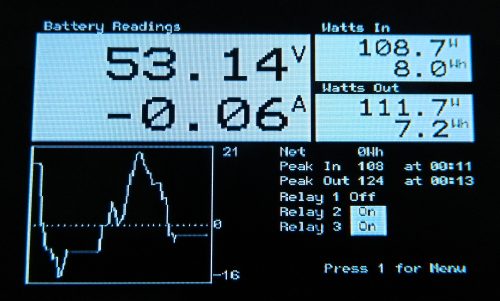
And a shot off the normal screen, 
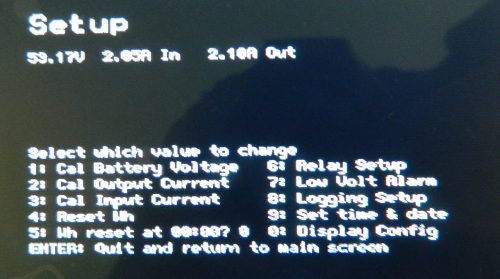
And the menu screen. 
The controller monitors battery voltage, battery current in and battery current out. From this it calculates the watts and watt hours flowing into and out of the battery bank. It displays the battery voltage, net current, watts and watt hours into the battery, watts and watt hours out of the battery, net watt hours, and peaks. There is also a running graph of the last 2 minutes of net battery watts. The graph is updated every second, while the rest of the display is updated 4 times a second. The controller has 3 independently set relay outputs for operating diversion/dump loads or shutting down a windmill. Plus there is a low battery alarm and data logging to the SD card in intervals of either 1 minute, 1 hour or daily. Its based on a DuinoMite-mini, though could use any of the Maximite series. Display is a little 4.5inch LCD monitor. It's a work in progress, I'll post more soon. Glenn The best time to plant a tree was twenty years ago, the second best time is right now. JAQ |
||||
| djuqa Guru Joined: 23/11/2011 Location: AustraliaPosts: 447 |
One word Excellent Looking good VK4MU MicroController Units |
||||
Bryan1 Guru Joined: 22/02/2006 Location: AustraliaPosts: 1344 |
Hi Glenn, That project does look great mate and it would be good to see the source and schematics etc as I do think this project could be the basis for other people not only to use but to tweak for their own system. I did look at those small VGA screens but the missus said cash converters did have a heap of lcd's there and all different sizes and cheap too. So Saturday morning I'm off with my Duinomite mega and keyboard and will be testing some of them out. Regards Bryan |
||||
| Gizmo Admin Group Joined: 05/06/2004 Location: AustraliaPosts: 5078 |
Hi Bryan Yeah will be putting a page together with the circuit, code, etc. The little screen I have is PAL, so the Maximite runs in 304X216 pixel mode, meaning screen space is tight. But thats OK, the text is so small anyway that from 1 meter away my old eyes cant read it  Thats why I've used larger fonts for the critical numbers and reverse video for the relay states. Thats why I've used larger fonts for the critical numbers and reverse video for the relay states.
Glenn The best time to plant a tree was twenty years ago, the second best time is right now. JAQ |
||||
donmck Guru Joined: 09/06/2011 Location: AustraliaPosts: 1313 |
Glenn, I have the same screen as you, and you are using a DuinoMite-Mini. If you haven't done so already, can you try setting it to NTSC-480 in the "setup" menu and see what happens. Cheers Don... https://www.dontronics.com |
||||
| Gizmo Admin Group Joined: 05/06/2004 Location: AustraliaPosts: 5078 |
Hi Don Tried the NTSC-480 mode, looks good and gives some more pixels across the screen I could use. But as I plan to put this project together as an article for the main web site, I want to keep it compatible with all the Maximite range, maybe later when its finished and I can modify it for my own use only. Glenn The best time to plant a tree was twenty years ago, the second best time is right now. JAQ |
||||
| cmichaelcouch Newbie Joined: 23/10/2011 Location: United StatesPosts: 16 |
I'd definitely like to see the schematics on this one as I have the duinomite-mini and want to do many of the same things with it. Also would like to adapt this for other projects. Michael Couch |
||||
| cmichaelcouch Newbie Joined: 23/10/2011 Location: United StatesPosts: 16 |
I think the main thing that I need right now is individual schematics for the different pin functions applications 1-9. And precise instructions for how to use them on the Duinomite-mini. For instance I'm not worried about using the Uext, or RS232 connectors. The only thing I'm worried about is the VGA and the SD card. So, I'd like to know exactly what pins this adds to my availability and how to access those pins without cutting traces etc. so I could leave the RS232 and UEXT as they are but still use the pins that make up those connections. Incidentally, I took an old standard PC cable and cut off part of it leaving the 26 pins the cable and the other two connectors to play with. I can insert LED and resistor leads into these other female pin holes to use as a Kluged proboard of sorts. But It is breaking my mind trying to figure out what I can plug in where. I was unable to understand much of the writting on this. People refering back to the PIC32 pin outs, etc. All the pin charts etc. is really confusing. What I need is a chart just for Duinomite-mini that says... Here are all the pins you can use. Here is how to use them as is. Here is what you connect to these pins for function X (1-9)(a schematic of the resistor, switch, opto, whatever is required to use the pin for the function. All of this using the MMBasic Pin() commands and the 26 pin connector numbers. Maybe we need a new protocol for naming this like Duinomite-miniMMBasicPin(X)GPIO(y) abbreviated DMMMMBPin(x)GPIO(y). I get crosseyed looking at all those charts, reading the descriptions and trying to figure out what I can do with the GPIO pins. We need something to make it easier. MMBasics main attraction for me was the familiar language and the easy Setpin and Pin() statements. These two reasons determined my using this device. Oh and the standalone operation with the keyboard and monitor. Another great thing would be a small cheap portable monitor that would handle all the resolution and just plugged up to the VGA. Could any of the Digital Picture Frames be used for that as is? Do they have VGA inputs? Michael Couch |
||||
| djuqa Guru Joined: 23/11/2011 Location: AustraliaPosts: 447 |
Buy one of the Very CHEAP 3.5" /5"/7in LCD monitors sold for reversing monitors as cheap as $20USD for a 3.5inch. STD VIDEO in and NTSC/PAL. Cheaper than any PhotoFrame That is what GIZMO is using for his display. VK4MU MicroController Units |
||||
| Gizmo Admin Group Joined: 05/06/2004 Location: AustraliaPosts: 5078 |
Fortunately this project is only using 6 of the Maximite IO pins, pins 1 to 6, and these dont conflict with the other accessories ( SD Card, etc ). At a later date I may look at adding more functions, like battery temp, etc, but until then, 6 pins is enough. The ciruit is pretty basic. 3 pins are for the relays, driven though a opto-coupler. You see, I have a pile of old computer boards, so tend to design my circuits to use components I can salvage form those boards. In this case, I'm using the opto-coupler driven relay circuits as used on these old boards, but a transistor driven relay, or a directly driven reed relay could work just as well. For the inputs I'm still undecided. Voltage is easy, a resistor divider, plus protection diodes for the Maximite input. Current, not 100% sure on what path yet, but looking at using a couple of op-amps and shunt resistor combination. The shunt resistor will be a length of steel thread, used this type of setup before and its works well. Still we only get like 0.1 volts per 100 amps, so a op-amp set up with a gain of 30 would be needed. Geoff mentions a OPA251 for precise low voltages, but Jaycar dont list them, so might look at alternatives, any suggestions? Or I may go for a current transducer or a hall sensor like the Alegro sensors. These get a little more expensive, and are bi-directional so will need a off-set implemented in the software. Other than that there is a 5v regulator, and thats it as far as circuits go. Glenn The best time to plant a tree was twenty years ago, the second best time is right now. JAQ |
||||
elproducts Senior Member Joined: 19/06/2011 Location: United StatesPosts: 282 |
I wasn't aware of these monitors until this post. What a great tip. I've been looking for low cost VGA monitors but this is a much better solution. Thanks. The project looks awsome. www.elproducts.com |
||||
donmck Guru Joined: 09/06/2011 Location: AustraliaPosts: 1313 |

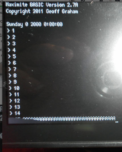
I received a badly manufactured screen, see bottom left hand corner. This is running on a DuinoMite-Mega in NTSC-480 mode. Just sent him this image, see how I get on with a replacement. Pay your money, take your chances. 
Cheers Don... https://www.dontronics.com |
||||
| ksdesigns Senior Member Joined: 25/06/2011 Location: United StatesPosts: 143 |
I use one from a car dvd player the kind that go on the back's of the seats got a few of them at a thrift store for like 10$ and were new also :) plus they have audio ken |
||||
| cmichaelcouch Newbie Joined: 23/10/2011 Location: United StatesPosts: 16 |
Is there a regular source for these at >$20? Also, the electonics explanation for input circuits was way over my head. I'm a board leve PC tech. Zilch in the way of component level knowledge and experience. Just trying not to blow up my Duinomite-mini. Need EXACT SCHEMATICS to follow. Michael Couch |
||||
| Gizmo Admin Group Joined: 05/06/2004 Location: AustraliaPosts: 5078 |
Hi Michael Like a lot of my projects, this one assumes a certain level of competency with component level circuitry. I design and build the circuit to suit my needs, then share the info so others can learn from it and modify it to their own requirements. Plus, we are only looking at a small part of the complete RE system ( wind, solar, etc ), and these systems usually have dangerous potential levels of current ( see: vaporised screwdriver ), and sometimes lethal voltages ( see: coffin ). For those reasons I would suggest you avoid this project, but keep an eye out for others that might be more practical for you. Same applies to the software side of things. Some members are good with component level electronics, or mechanical, but dont follow the software, and again this isn't the sort of project for them. Glenn The best time to plant a tree was twenty years ago, the second best time is right now. JAQ |
||||
| Gizmo Admin Group Joined: 05/06/2004 Location: AustraliaPosts: 5078 |
Had a chat to Pete (downwind) tonight about the current sensing side of things, and he suggested I look at the Alegro ACS758 series of sensors chips in the unidirectional range. These will measure current in one direction only, so we get an improved resolution, 0 - 5 volt for 0 to max current instead of 2.5 - 5 volt for the bi-directional chips. Also the bi-directional chips can be a bugger to zero, the 2.5 volt mid point is dependant on the 5 volt supply, any drift in the supply and you can be reading plus or minus a few hundred milliamps. I've ordered a 100 amp and 200 amp chip. The 100 amp chip means I can measure up to 5kw input power to the batteries, and the 200 amp chip will let me measure up to 10kw drain, based on a 50 volt battery bank. I've been working on the software. Changed the running graph to display either the last 120 seconds, 120 minutes, or 120 hours ( 5 days ). I dont want to post the code just yet, its very messy and I'm still adding features. But as soon as its done and the controller is working I'll post it. Glenn The best time to plant a tree was twenty years ago, the second best time is right now. JAQ |
||||
| Olimex Senior Member Joined: 02/10/2011 Location: BulgariaPosts: 226 |
Glenn you can also check this http://www.ti.com/product/ina226 it's I2C and easy can be interfaced to MM/DM |
||||
| jebz Regular Member Joined: 13/06/2011 Location: AustraliaPosts: 79 |
It's great current and voltage monitor especially useful for solar monitoring. INA226 is available from Farnell. |
||||
| Olimex Senior Member Joined: 02/10/2011 Location: BulgariaPosts: 226 |
and we are working on INA226 UEXT module which will be available in January 
note that many INA226 can be connected to different I2C adresses |
||||
Downwind Guru Joined: 09/09/2009 Location: AustraliaPosts: 2333 |
The INA226 is not a overall good choice other than its I2C functions, due to the fact its limited to 40 volts input and many systems way exceed this, I have used many of the TI shunt monitor chips and the better ones to use are the INA195 (or INA193, INA194, INA196, INA197, INA198) as they have a 80 volt input and are a 5 pin package that is much easier to work with at the hobby level. (albeit still a tiny chip) By the time a suitable shunt is installed and the circuit assembled for monitoring, the size and cost is no better than the Allegro chips that give a far better full range readings and with the benefit of 100% isolation from the high voltage side. (also can be used as high side or low side monitors) After years of using many different current monitoring solutions my conclusion is the small price of the Allegro is well worth the cost. Lesser current monitoring solutions give greater variance in the readings, resulting in crap data being recorded. When as much time and effort has gone into developing a system as Glenn has done, than to try to save $2.00 on a cheaper solution to me is far more expensive in the long run. BTW. nice work Glenn. Pete. Sometimes it just works |
||||
| Page 1 of 3 |
|||||