|

|
Forum Index : Microcontroller and PC projects : (DM) Internal "shield"
| Author | Message | ||||
| vasi Guru Joined: 23/03/2007 Location: RomaniaPosts: 1697 |
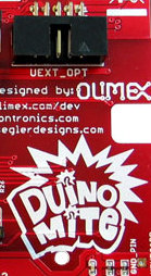
Duinomite needs an Eagle "prototyping" board (an empty board/project) for this area (including the screw?): 
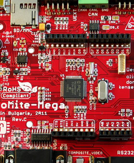
Also, apparently, there is more space for Arduino shield than on the original Arduino board but, if those connectors collide with the shield, then a proper empty Eagle shield is required: 
Hobbit name: Togo Toadfoot of Frogmorton Elvish name: Mablung Miriel Beyound Arduino Lang |
||||
| vasi Guru Joined: 23/03/2007 Location: RomaniaPosts: 1697 |
More. I didn't saw any documentation of the board but I suggest to make something like this: On an outlined graphical image of the board (where only the board margin and connectors are made visible), when a connector is used (chose your highlighting color), the available connectors must be colored in green and the restricted ones in red. Hobbit name: Togo Toadfoot of Frogmorton Elvish name: Mablung Miriel Beyound Arduino Lang |
||||
bigmik Guru Joined: 20/06/2011 Location: AustraliaPosts: 2914 |
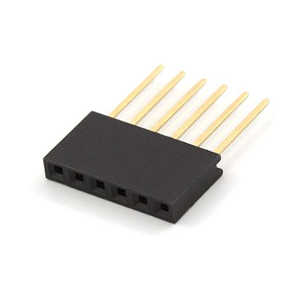
Hi Vasi, Not exactly sure about your question, but that section is for an INTERNAL UEXT pcb, For example a blue tooth or wireless board that is small and can be mounted internally to the case and still leave the external UEXT socket for other peripheral, as in the MOD-IO board or any others.. If you are talking about a physical clash of a particular Arduino shield and the DM then of course simple header pins can be installed to raise the shield slightly to provide clearance, as in these type of pins... 
Mick's uMite Stuff can be found >>> HERE (Kindly hosted by Dontronics) <<< |
||||
| Olimex Senior Member Joined: 02/10/2011 Location: BulgariaPosts: 226 |
I'm not sure I understand what Vasi wrote either, at the moment MOD-BT, MOD-WIFI, MOD-NRF24LR will fit inside without problem and the normal Arduino shields also can be put on DuinoMite mega if it's not boxed |
||||
| vasi Guru Joined: 23/03/2007 Location: RomaniaPosts: 1697 |
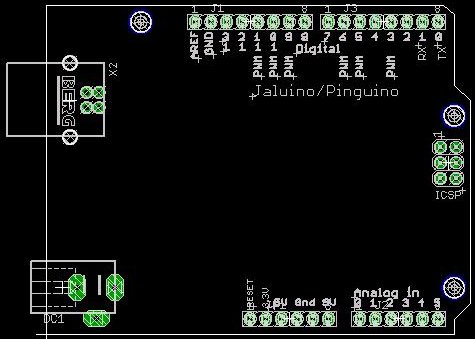
Hi guys, I know the role of the internal UEXT. And I know that you think from the producers perspective. I'm thinking from the user perspective. But not just a beginner which only buy modules and learn how to use those in his projects. On the Arduino world there are also shields for rapid prototyping. Or, for more advanced users which want to design their own shields, there is an empty Eagle project for that, where the limits, and some connectors which interfere with the shield are placed in order to avoid them at design time. In this respect, is good to know if some of the DM connectors are interfering with a possible larger Arduino shield that the standard one. If yes, then those limits and colliding connectors must appear in that Eagle project of a clean shield. For the internal UEXT, an Eagle project can be made by Olimex, as they know the exact dimensions. Help the community to design their own shields if they want to. This is an example of a standard Arduino shield: 
On an original Arduino, the shield can go beyond the margins of the "motherboard" having, virtually, no limits on dimensions. How large can be a shield on DM boards, On which margin is limited by a colliding connector (if any)? All details can be specified on an empty Eagle project for DM shields. Vasi Hobbit name: Togo Toadfoot of Frogmorton Elvish name: Mablung Miriel Beyound Arduino Lang |
||||
| vasi Guru Joined: 23/03/2007 Location: RomaniaPosts: 1697 |
And then, having a lot of noise an probably electrical contact problems... Anyway, it will help a lot if we will have a basic Eagle project with maximum dimensions and eventual obstacles posted as a second "silk screen" on the shield. And the right dimensions and form for the internal UEXT board (another Eagle file, of course). Hobbit name: Togo Toadfoot of Frogmorton Elvish name: Mablung Miriel Beyound Arduino Lang |
||||
Bryan1 Guru Joined: 22/02/2006 Location: AustraliaPosts: 1344 |
Hi vasi, There is a breakout shield board that connects to the 26 pin connector too if you didn't know. I've just designed up a RS232E shield board to use for my printer project as I don't want to risk the onboard RS232 chip. I'll be tranferring the pcb image via my usual method of the iron on as I have found it gives far better results than 2 copies stuck together and doing the UV method. Anyway if any other guys are using Sprint Layout for pcb design that Adruino pinout is saved as a macro and I'll be happy to share it if anyone wants it. Regards Bryan |
||||
| Olimex Senior Member Joined: 02/10/2011 Location: BulgariaPosts: 226 |
The DuinoMite Eagle files are available for download, to make your own shield all you have to do it to delete the components which you will not use, the Arduino connector is there so you can use it for your shield and add the custom circuit you want around it. |
||||
| vasi Guru Joined: 23/03/2007 Location: RomaniaPosts: 1697 |
Well, that is not needed because a footprint Arduino shield already exist in Eagle format. Take a board larger than DM and try to stick it in Arduino sockets. If there are some obstacles, then you have some restrictions so, a new Eagle footprint is required. If not, doesn't matter. Also, for internal UEXT is not so simple. Is about an angled female connector which enter in the UEXT connector and that means the board must slide and, you have some cuts there and a screw... I think that is a job for Olimex. Hobbit name: Togo Toadfoot of Frogmorton Elvish name: Mablung Miriel Beyound Arduino Lang |
||||
donmck Guru Joined: 09/06/2011 Location: AustraliaPosts: 1313 |
Sorry Vasi, I am having trouble following you on this. The internal UEXT is for things like the RTC module, this will be on a short cable, and be mounted much like any board has been mounted inside the Altronics MaxiMite case. This usually means double sided tape. If you mean to use an Arduino shield and a module that uses the UEXT internal connector at the same time, I don't see a problem, apart from putting the lid on the case, if that is what you want to do. However this has all been allowed for with a very cheap external shield convertor, and the UEXT module can be plugged internally or externally. As far as shields hitting connectors on the MEGA, every shield I have tried (admittedly I don't have a lot) fit without fowling with any connectors or components. You won't be able to put a lid on an LCD shield, but then you wouldn't want to. Cheers Don... https://www.dontronics.com |
||||
| vasi Guru Joined: 23/03/2007 Location: RomaniaPosts: 1697 |
Then, forget it... it doesn't matter. Sorry for trouble. Hobbit name: Togo Toadfoot of Frogmorton Elvish name: Mablung Miriel Beyound Arduino Lang |
||||
| rhamer Senior Member Joined: 06/06/2011 Location: AustraliaPosts: 174 |
What Vasi is saying is he would like to see a PCB layout template created that people can use if they wanted to create their own boards to plug into the various DuinoMites. These templates would have the absolute maximum dimensions that will fit into each location for each DuinoMite board. So for example, if I decided to make a super gadget board that I wanted to plug straight into the internal UEXT connector, I just grab the template that has the maximum outer dimensions, the location of the plug in connector and where any mounting screws might be and use it as the basis of my board. That way I dont have to measure it up myself, and I know it will fit. The same thing applies to the Arduino connector, so a person can make their own board as big as they can and know it will fit. Cheers Rohan Rohan Hamer HAMFIELD Software & Hardware Solutions Makers of the Maximite Expander. http://www.hamfield.com.au |
||||
bigmik Guru Joined: 20/06/2011 Location: AustraliaPosts: 2914 |
Ahaaa... Thanks Rohan that makes sense to me.. Sorry Vasi, I know English is not your native tongue.. Yes I see what you mean that would be handy I only Use Protel design Explorer and never used Eagle so that would have to be something for Olimex to come up with, If I was to design a shield for the DM I would have to crank up the Vernier and measure these dimensions.. Good Point, See what Olimex can do, it should be easy enough to plot out from their existing eagle files. Regards, Mick Mick's uMite Stuff can be found >>> HERE (Kindly hosted by Dontronics) <<< |
||||
| Olimex Senior Member Joined: 02/10/2011 Location: BulgariaPosts: 226 |
ahaaaa this is really nice idea :) and very easy to implemet too |
||||
| vasi Guru Joined: 23/03/2007 Location: RomaniaPosts: 1697 |
Hi Rohan, thank you for your help. Your text was clear as crystal. Vasi Hobbit name: Togo Toadfoot of Frogmorton Elvish name: Mablung Miriel Beyound Arduino Lang |
||||