|

|
Forum Index : Microcontroller and PC projects : (DM) I2C BUS (SDA1 & SCL1) on DM Mega.
| Author | Message | ||||
| DuinoMiteMegaAn Senior Member Joined: 17/11/2011 Location: AustraliaPosts: 231 |
Per rev.C DuinoMite Mega schematics -- the red dots indicate 5 VDC tolerant inputs and OC outputs? So the I2C bus (A4 & A5 or PIN5 & PIN6) is 5 VDC tolerant BUT since you have the 4.7K pullups tied to +3.3 VDC then this I2C bus can only be used with 3.3 VDC I2C devices? Am I correct? If I wanted to use a 5 VDC RTC (DS1307), I would have to remove the on-board 4.7K pullups and use external +5 VDC pullups for this device? Of course, mixing 3.3 VDC and 5 VDC I2C bus devices should never happen on this board. |
||||
| vasi Guru Joined: 23/03/2007 Location: RomaniaPosts: 1697 |
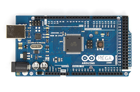
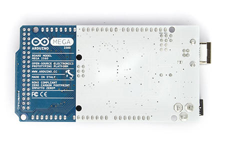
The problem with 3.3V devices is that you must stick in that area and make conversions as rare as possible. It force you to rethink your strategy. A good 5V (still) board is an Arduino Mega 2560. 
 Hobbit name: Togo Toadfoot of Frogmorton Elvish name: Mablung Miriel Beyound Arduino Lang |
||||
| ksdesigns Senior Member Joined: 25/06/2011 Location: United StatesPosts: 143 |
Well you have to understand that I2c Devices are open collector on SCL and SDA so it does not matter if you power the I2c Device from +5v or +3.3v they only pull the bus low they do not source current on them bottom line is bus voltage does not matter on I2c bus that much ken |
||||
| JohnS Guru Joined: 18/11/2011 Location: United KingdomPosts: 3800 |
Thanks for posting that. John |
||||
| Keith W. Senior Member Joined: 09/10/2011 Location: AustraliaPosts: 118 |
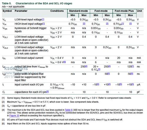
Regarding I2C SCL SDA input voltage specifications. The data sheets for I2C devices that I am now using, from STMicro, NXP and Maxim, all specify the input high level (minimum) at 0.7 of the supply voltage. That is 3.5 volts required input with a 5 volt supply to the I2C chip. I think an inadequate margin with only a 3.3 volt supply to the SCL and SDA pull up resistors. Yes it might work, sometimes. Keith W. |
||||
| DuinoMiteMegaAn Senior Member Joined: 17/11/2011 Location: AustraliaPosts: 231 |
I think an inadequate margin with only a 3.3 volt supply to the SCL and SDA pull up resistors. Yes it might work, sometimes.
Right now, the DM Mega on-board I2C bus 4.7K pullups are tied to 3.3VDC! So you are saying it might work? |
||||
| Olimex Senior Member Joined: 02/10/2011 Location: BulgariaPosts: 226 |
this depend on your 5V device, if it accepts 3.3V as "1" there will be no problem if not you can just add 5V pullup, the I2C port is 5V tolerant to nothing wrong will happend to DuinoMite |
||||
| DuinoMiteMegaAn Senior Member Joined: 17/11/2011 Location: AustraliaPosts: 231 |
the I2C port is 5V tolerant to nothing wrong will happend to DuinoMite
You need to fix your DM user manual MM-BASIC can access ARDUINIO SHIELDS with the PIN() function.
Next ports could be digital inputs, digital outputs and analog inputs, note max voltage to these ports should not exceed 3.3V or they will be damaged: ARDUINO.A0 �� PIN(1) ARDUINO.A1 �� PIN(2) ARDUINO.A2 �� PIN(3) ARDUINO.A3 �� PIN(4) ARDUINO.A4 �� PIN(5) <------------------ I2C ARDUINO.A5 �� PIN(6) <------------------ I2C |
||||
| ksdesigns Senior Member Joined: 25/06/2011 Location: United StatesPosts: 143 |
From the I2c spec I2c Spec [1] Some legacy Standard-mode devices had fixed input levels of VIL = 1.5 V and VIH = 3.0 V. Refer to component data sheets. 
ken |
||||
| DuinoMiteMegaAn Senior Member Joined: 17/11/2011 Location: AustraliaPosts: 231 |
if not you can just add 5V pullup
This means that I would have to hack or remove the on-board 4.7K pullup resistors, which is no small task. It would have been nice if there was a jumper to remove to float the pullups? |
||||
| DuinoMiteMegaAn Senior Member Joined: 17/11/2011 Location: AustraliaPosts: 231 |
@Ken I was able to get the Maxim-IC DS3231 I2C +-2 PPM real time clock to work with the DuinoMite. Of course, this is a 3.3 - 5 vdc device but I chose 3.3 VDC because I lose the +5 VDC when running on LiPo battery. BWT ... It is nice having a RTC that only loses 1 second in 23 days! Other RTC of +-20 PPM loses over 5 minutes a year! |
||||
| Olimex Senior Member Joined: 02/10/2011 Location: BulgariaPosts: 226 |
If you check DuinoMite schematic SCL1 go to UEXT.5 and SDA1 go to UEXT.6 these are RD9 and RD10 ports of PIC32 which are 5V tolerant. so you have to attach 5V I2C device ONLY to UEXT.5 and UEXT.6 SCL1 and SDA1 are also wired through 330 ohm resistors to ARDUINO.A4 and ARDUINO.A5, and provide I2C functionality to Arduino platform, but these are only 3.3V ports so you should *never* attach 5V I2C device to A4 and A5 as they go to RB8 and RB9 which are not 5V tolerant and will damage them. The purpose of the 330 ohm resistors is to protect RB8 and RB9 as there are clamp diodes on RB8 and RB9 and even if you attach 5V device to UEXT.5/UEXT.6 it will not damage RB8, RB9 as the excess voltage will drop on these resistors. I hope now is clear :) |
||||
| Olimex Senior Member Joined: 02/10/2011 Location: BulgariaPosts: 226 |
first you should try as your I2C device may work on 3.3V levels if it doesn't work just add 4.7K pullup to 5V on UEXT.5 and UEXT.6 |
||||
| DuinoMiteMegaAn Senior Member Joined: 17/11/2011 Location: AustraliaPosts: 231 |
@Olimex The reason why I had so many questions is that I tried to duplicate "CrackerJack's DS1307 analog clock" on the MaxiMite. He used the +5 VDC DS1307 I2C RTC on the Maximite which has no "built-in" I2C pullups resistors. I tried to use the same DS1307 I2C RTC on the DuinoMite and it did not work. First of all, the DS1307 is only a +5 VDC device and it will not run at 3.3 VDC. Second was the "pullup" issue in this topic. I decided not to hack to board to make this device work but decided to use the 3.3 VDC precision +- 2 PPM I2C DS3231 (drop-in replacement) RTC in its place. It works.  |
||||
| DuinoMiteMegaAn Senior Member Joined: 17/11/2011 Location: AustraliaPosts: 231 |
just add 4.7K pullup to 5V on UEXT.5 and UEXT.6
Sure BUT I would have to FIRST remove the 4.7k on-board pullups to 3.3 VDC - which is no small task considering they are SMD devices? 
If not, then what I would be doing is putting two (5vdc) pullup resistors in parallel with two (3.3VDC) on-board pullups which does not make any electrical/electronic sense whatsoever (4.7k in parallel with 4.7k = 2.35K) I believe you are inferring to remove the on-board 4.7K pullups FIRST and THEN add 4.7K pullups to +5 vdc externally. BTW ... Like I said before, I just put a precision I2C +3.3 VDC RTC (DS3231) on A4 and A5 and be done with it. 
The watch crystal on the DS1307 loses about 5-10 minutes per year. 
The TXCO on the DS3231 loses about 1 minute per year. 
|
||||