
|

|
Forum Index : Microcontroller and PC projects : sparkey`s spot
| Page 1 of 4 |
|||||
| Author | Message | ||||
| sparkey Senior Member Joined: 15/06/2011 Location: AustraliaPosts: 819 |
using the bread board expander from "hamfield" it could be reveresed as such that with my mod of fitting an double lenth bread board and a couple of rubber feet at the far end of the board it would be a great project for plugging in an "ev" minimite and there for connecting up a 12 volt 1 amp plug pack you will have all the voltages u need ...also this will allow u to connect a ribbon cable to the board with the capeabilty of reverse wiring .. to the cable sockets on the board then you will have the "mini" with a power supply and cable out to plug into what you may like to ...also for the young and not so young ...and you may want to change the 12 volt reg for a 9 volt reg but thats up to you ..and really if you are going to use the 12 volt rail it would be wise to use a 14 volt dc supply ...the "7812" can be directly replaced with a :7809 : TO 220 package and if you are still running 14 volts this will be fine ....there other possabilitys that this may have this is just one of my ideas ... technicians do it with least resistance |
||||
| sparkey Senior Member Joined: 15/06/2011 Location: AustraliaPosts: 819 |
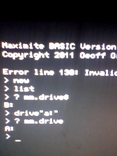
i have read that hyper terminal wont send files to "DRIVE A" IT CAN BE DONE BUT ITS A LITTLE TRICKY read this whole article before going ahead....important.... ok open up a hytrm at 9600 using what ever com port you have allocated to the silicon chip com port call it maxi and select a picture ... open it ... hit the space bar you should be logged onto the maximite now check to see which drive you are logged onto ...log onto DRIVE A ... type " XMODEM RECIVE "set.bas" example name given here.... enter these following steps must be done before the connection times out you will be seeing dollar sign`s going accross the screen....this is the counter ... make shure you know where exactly your file is on your pc-hdd ... in the hy-term select transfer select send file when the browse screen appears select your file to be transfered select :protocal::"xmodem" select your file ..click send ... all these steps must be done before the dollarsigns stop counting if you have done this correctly your file will start to transfer to DRIVE A ..... ..regards sparkey....///...// technicians do it with least resistance |
||||
| sparkey Senior Member Joined: 15/06/2011 Location: AustraliaPosts: 819 |
may be what you could do is cut the tracks to con three on the "mini" and solder in a 3.3 volt reg into these holes with a bolted up heat sink standing verticaly....and there is pin 2 on this con 3 that actully goes to the three volt rail hard wiring it into the cct adding ca couple of caps should not be to difficult ,.. my thereoy and two bob`s worth...///.../// also if you dont require a heat sink on it put some heatsrink over it and lay it down horizontally...///.../// also in addition there is some blank space on the end of the board not shure if there is enough but you may be able to mount a dc power sckt there drill out some holes and wrap a cabl tie around it to hold it in place...///.../// :wire wrap the pins from the dc-pwr sckt to the appropiate pins on the reg with positive going to the input pin on the reg a negative going to ground ...also the cable tie goes around and through the board to secure it you will also need to drill the holes for what ever pins that are on the particiular socket you are using ....regards spoarkey technicians do it with least resistance |
||||
| sparkey Senior Member Joined: 15/06/2011 Location: AustraliaPosts: 819 |
i would also like to note that i do not have the hard ware yet to show pics and stuuf on how my idea of the addon 3.3 volt reg is done but as soon as i get one i will be doing the mod and will show picks then ...regards sparkey... technicians do it with least resistance |
||||
| sparkey Senior Member Joined: 15/06/2011 Location: AustraliaPosts: 819 |
also when i do mountt 3.3 volt reg i am using a ts2940 for this you may use what u like as long as you get the pinouts correct ..just that i have easy access to these atm ...regards ...///dont forget to run the ground from the pwr supply "negative" to the reg pin gnd as this may cause some sort of grnd loop ..if not done...and the voltage may soar from the reg ...not a good thing......///...///::: ::and if you do the vreg mod you will still have acess to the tracks as to mount up an rtc if you want as i am only useing the 3.3 volt ral and ground///you can just wire wrap yhe "rtc" and piggy back it around where u like...///.../// ::another point i would like to add if u do use a heat sink i would advise useing an insulating kit for the regulator...so its neigher high or low.... altrnics taking orders for mini technicians do it with least resistance |
||||
| sparkey Senior Member Joined: 15/06/2011 Location: AustraliaPosts: 819 |
altronics taking orders for "mini"maximite technicians do it with least resistance |
||||
donmck Guru Joined: 09/06/2011 Location: AustraliaPosts: 1313 |
As this is your spot Sparkey, I thought I would post this here. You have asked me several times about a VGA to PAL adapter that I don't have. Aargee has also answered this question in another thread. You need to click on the link marked <<HERE>> and you will find out what it is. Cheers Don... 
http://www.googe.id.au/Blog/Entries/2011/7/13_Scratch_Built_ Maximite.html ==================== sparkey wrote: also i think that don has a plug in adaptor to plug straight to the vga with a pal sckt on it dont know weather he stil has them or if it was a one off maybe you should pm him ...regards sparkey.../// aargee wrote: Home made, look at my link below. __________________ My Maximite ramblings are <<HERE>> https://www.dontronics.com |
||||
| sparkey Senior Member Joined: 15/06/2011 Location: AustraliaPosts: 819 |
this one has got me how do we end up with a flash drive of 256 k when we only have 128k of system ram although i gues most singular programes may not utilize the full 128k but seem`s a little odd,,,.../// technicians do it with least resistance |
||||
| Greg Fordyce Senior Member Joined: 16/09/2011 Location: United KingdomPosts: 153 |
Easy, the flash and ram are seperate areas of the pic. The ram is the same as on your pc, when you turn off the power it loses it's data but doesn't suffer from the limited write cycles of flash. So the pic uses ram to run your programs and flash to store them. Hope this makes sense. |
||||
| sparkey Senior Member Joined: 15/06/2011 Location: AustraliaPosts: 819 |
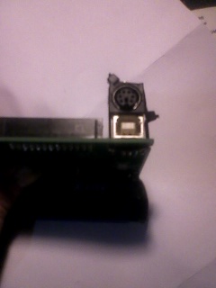
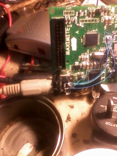
some pics of my modified maxi "ev" thanks to don for the board its not one of his new boards its an early model i have cabletied the k-b sckt on top of the usb port and added the approite pins so i can get compisite pal out of it more pics to come later...yes you could call it "boredom" but nesessaty is the mother of invention...enjoy...///.../// 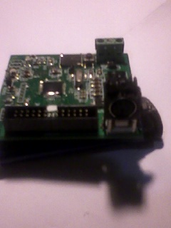
key board connected and working... technicians do it with least resistance |
||||
| sparkey Senior Member Joined: 15/06/2011 Location: AustraliaPosts: 819 |
ok here we go i have the k-b connected running of compisite pal ...will connect up the vga and a comm port when i get the connectors and here`s some pic`s regards sparkey ..enjoy.../// 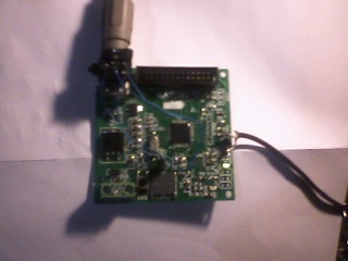
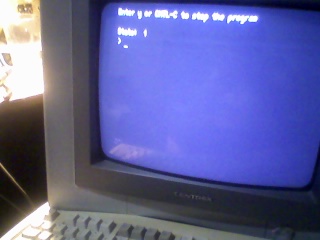 sorry about the focus i only have a mob phone as a cam and it dont like crt`s much but here ya go....//// sorry about the focus i only have a mob phone as a cam and it dont like crt`s much but here ya go....////
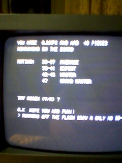
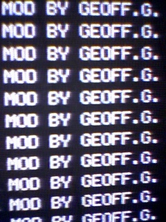
just a few more pic`s showing that geoff`s pal mod works and seems quite steady....///.../// 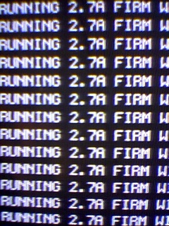
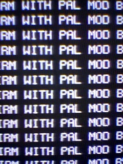
technicians do it with least resistance |
||||
| Keith @ Senior Member Joined: 19/06/2011 Location: AustraliaPosts: 167 |
Sparkey Is that a dope butt in the tin? The more we know, the more we know we don't know ! |
||||
| sparkey Senior Member Joined: 15/06/2011 Location: AustraliaPosts: 819 |
heres the hex file gerard and the code 2011-10-30_114638_invtr.zip the picture is like seeing double one on top of each other but double readings.../// thank you here is a picture of my pal to vga converter and also a pic of this running my lcd screen.../// 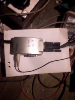
 this is the k-board wiring i`m soorry about the quality of the pic but enlarge it and u will get the wiring only four wires ..../// this is the k-board wiring i`m soorry about the quality of the pic but enlarge it and u will get the wiring only four wires ....///
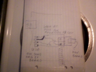
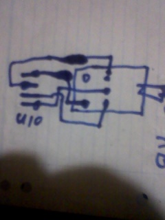
sorry i should mention that i have the kb-sckt fitted up side down with the pins sticking up in the air once you have connected the wires just put a dab of silastic silicon sealent glue over the pins let it dry over night this will keep them from comming off and also insulate it ... :this is a pic of a vga cable sockt as i am going to atempt to pin it out and connect it to the "ev" board " 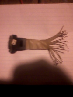
well sorry guys i could not get the vga to work there may be some other reason i will have to go over this for a while considering that the comp`s works maybe i did not have it right will keep trying though ...///.../// technicians do it with least resistance |
||||
| sparkey Senior Member Joined: 15/06/2011 Location: AustraliaPosts: 819 |
ok now ::there is a mistake in the vga pinouts in silicon chip mag and i think its the reason i failed in my attempt::::march silchip shows the "horiz" connected to pin 12 ...and nov shows it connected to pin 13 i think 13 is prolly correct considering this board that i am using has never ben used for vga video before...regards ....pin 13 is correct houston we have vga liftoff... 
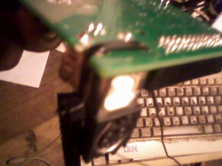
given it is a little messy i connected the ground and video feed straight to the pal hedder and the horiz & vert to the board its still prototype atm but will neaten it up as soon as i decide how to...lol...///.../// well i am going with the compisite output as the resulution of it is some what larger in pixels....and this pic is for gerard... 
technicians do it with least resistance |
||||
| sparkey Senior Member Joined: 15/06/2011 Location: AustraliaPosts: 819 |
after looking at pins 4 and five on the sm1 cct i see that they are pinned out to "U11" connector on the "ev" board from don so i am going to mount my ev board to one of my scrap sm1 boards and isolate the rtc from the sm1 board and connect it into the "ev" board as i am going to bolt the two boards together and create a maximite out of the two boards and also i will be useing the vga sckt of the sm1 board but leaving my K-B connector as is and i will have it running my inverter if all goes well i will be sending picks later to day ...ahhh monday arvo project what a perller...regards sparkey...///...// 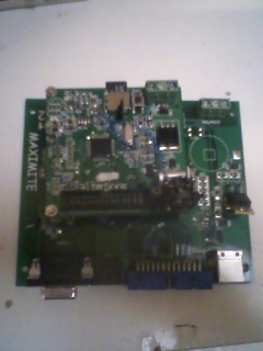
a better pic....... 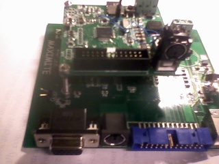
technicians do it with least resistance |
||||
VK6MRG Guru Joined: 08/06/2011 Location: AustraliaPosts: 347 |
What happened to the SM1 Maximite? Why did you scrap it?  Its easier to ask forgiveness than to seek permission! ............VK6MRG.............VK3MGR............ |
||||
| sparkey Senior Member Joined: 15/06/2011 Location: AustraliaPosts: 819 |
well i have blown up 3 of them ..fist clumsy mistake second,third wiring back with the trim pots wound the wrong way needless to say i use the parts of them for other things and i will prolly use the rtc kitset i have 2 of them complete parts just need to isolate the cct from the sm1 and go from there ...i think that sums it up for you ...so there ya go there not industructable as one might think but in the early days of the inverter the wiring was a mess its a lot better now as i have basically finished it and the maxi is running in pwm mode...regards sparkey... and here is a pic of it running have the usb for power atm until ifit it into the inverter as it has also the video out hard wired with wire wrap wire its a little hard to se the wires but...i have drilled holes into the tracks to isolate the horiz.vert.video and ran a jumper eatrh from the supply sockests the green ones that extra gnd came in handy after all next is the rtc getting it going as you can see i dont have the key board plugged in atm...regards sparkey... 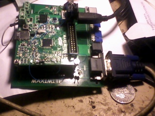
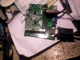
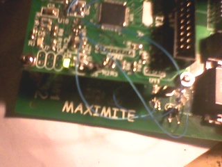
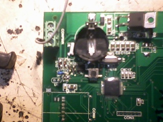
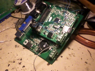
:;and yes we have left the tower it 3_38 whooo i have the time clock running not really shure how to set it correctly but its working ...here`s some pics... 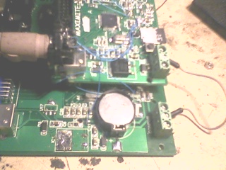
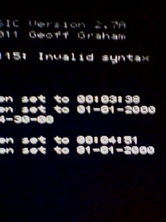
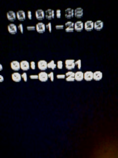
well i `v almost given up on this rtc thing well...one time the read program ran but most of the time i get error line 446 its anoying ..given that i dont really need the "rtc" i`m not too worried ... i have gone over and over it hard ware wise with a fine tooth comb ...ohh well i will still keep at it i must have had something right some time for the read program to read correctly ...???...,...///.../// technicians do it with least resistance |
||||
| sparkey Senior Member Joined: 15/06/2011 Location: AustraliaPosts: 819 |
seem`s no body really tells any body just how to do some things well :: ::heres how to set the "rtc":::: 1) powr up the maxi 2) enter the correct time and date::: 3) run the program that does the diag ..the one that lets you know its functioning correct you should get a result of zero here if you do not then something is wrong ...check over everything for faults weather they be hard ware or soft ware... 4) run the prog that reads and sets the time ... 5) you must do this in exact order that is why every body is getting error messages.... 6) put the time set program into your auto run list and you should be off and running... regards sparkey...///.../// technicians do it with least resistance |
||||
VK6MRG Guru Joined: 08/06/2011 Location: AustraliaPosts: 347 |
Sorry Sparkey, I beat you to it by almost an hour! Have a look at my post <<HERE>> Also, the reason I was getting error messages was because of the extra lines added and amended to the READ.BAS and WRITE.BAS files. Once these changes were made, my RTC worked! 
Its easier to ask forgiveness than to seek permission! ............VK6MRG.............VK3MGR............ |
||||
| sparkey Senior Member Joined: 15/06/2011 Location: AustraliaPosts: 819 |
you prolly had help but i had to figure it out for my self ..../// step i left out sorry before you nstart take the battery out then after step 6 and you have the correct time and date replace the battery...///.../// technicians do it with least resistance |
||||
| Page 1 of 4 |
|||||