|

|
Forum Index : Microcontroller and PC projects : Home-made single-side Maximite Board
| Author | Message | ||||
Sumit Newbie Joined: 13/09/2011 Location: Posts: 23 |
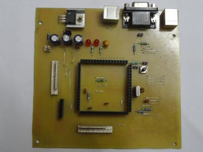
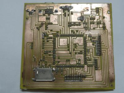
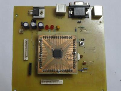
Here is my first attempt to a home-made single sided maximite board using the quick 'n' easy toner transfer method. It has some vias as expected but I think that is OK for a home-made design. It was built in under 2 hours including soldering and firing up the MMBASIC. It did not boot for the first time because I used capacitor "C5" as electrolytic. ITS VERY IMPORTANT TO USE A TANTALUM CAPACITOR FOR C5. Everything works as good as it was meant to be. Here are some pictures.... 


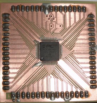
1.Back Side 2.Front Side 3.Front Side with PIC32 4.PIC32 adapter for easy replacement and soldering. Images may seem bad due to reflections. |
||||
| Geoffg Guru Joined: 06/06/2011 Location: AustraliaPosts: 3194 |
Wow, that is amazing. Did you make the carrier board for the PIC32? The tracks need to be very close together which is difficult on a handmade board. Also, what is the silver thing on the underside of the board? A shield? Bluetooth? Geoff Geoff Graham - http://geoffg.net |
||||
elproducts Senior Member Joined: 19/06/2011 Location: United StatesPosts: 282 |
I think that's the SD card socket. www.elproducts.com |
||||
Bryan1 Guru Joined: 22/02/2006 Location: AustraliaPosts: 1344 |
Wow that does look great for a homemade board WELL DONE, I did have a go at making my own on a kiwacan tqfp board but I couldn't get mplab to see the board and yes I did use an electro for C5. I do have some tantalums now so I might have to have another go at it. Cheers Bryan |
||||
| Gizmo Admin Group Joined: 05/06/2004 Location: AustraliaPosts: 5078 |
Yeah I agree, very good work Sumit. Glenn The best time to plant a tree was twenty years ago, the second best time is right now. JAQ |
||||
| sparkey Senior Member Joined: 15/06/2011 Location: AustraliaPosts: 819 |
i argree with others ..where did you get the cct board that holds the pic and have yo made full use of all the pins that are actully avaliable from the chip point of veiw technicians do it with least resistance |
||||
| Ray B Senior Member Joined: 16/02/2007 Location: AustraliaPosts: 219 |
Sumit, don't worry about the vias you did this on single sided board. What PCB design program did you use ? I'm just getting into Eagle and my first project is a MaxiMite I/O board extending all of the 26 pin connector out onto the board then have some I/O circuitry like MAX232, LCD connector etc. Something to replace what I currently have working on protoboard. One challange I have is using on a single sided board (my home brew choice) restricted by the free version of Eagle to a 80 x 100 mm board to have most of the 26 I/O connector pins traversing the board to an "exit" 26 I/O connector so I could in theory daisy chain boards. This will result in a lot of vias. Another option would be to have vertical daughter boards for the plug in options. When I have something usable I'll publish the source files on this forum to encourage others. RayB from Perth WA |
||||
Sumit Newbie Joined: 13/09/2011 Location: Posts: 23 |
Thanks to everybody for the appreciation !! 
I made the PIC32 adapter board using EAGLE version 5. I had to make my own device library because EAGLE does not have a PIC32 device library by default. For that, I had to edit the TQFP64 libraries from other devices eg. LPC2148 from NXP, that has the same package. It took some time but the effort is worth it. This enables me to re-design the main board without much effort since I already have the PIC32 "adapters" easily made. |
||||
haiqu Senior Member Joined: 30/07/2011 Location: AustraliaPosts: 152 |
I just have to marvel at that, Sumit. Quite an achievement indeed. Rob unzip, strip, touch, finger, grep, mount, fsck, more, yes, fsck, fsck, fsck, umount, sleep |
||||
| Dave Everett Regular Member Joined: 24/06/2011 Location: AustraliaPosts: 43 |
That's great work mate. While I have played with the toner method in the past, I find it too wasteful of toner. I use a photo etch process now and I have found my UV box works great with paper artwork, much better than acetate that I used to use. I regularly do 8mil traces and 8 mil gaps and always get perfect boards. Dave Everett |
||||
jman Guru Joined: 12/06/2011 Location: New ZealandPosts: 711 |
Hi Sumit Well done with the homemade PCB I have used the same method with good success Regards John |
||||